GEO M10 HARDWARE SETUP PROCEDURE Page 31/79
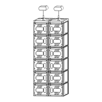
6.3.3 GEO M10 only on Touring Bumper with stacking extensions
Required item
- 1 x VNT-BUMPM10
- 1 x VNT-GSTKM10S
- 1 x VNT-GSTKM10L
IMPORTANT
Ground stack assembly BUMPM10 + GSTKM10S + GSTKM10L is rated for a maximum of
6 x GEO M10 in any inter cabinet angle configuration with +/-12° initial angle, provided
this device is assembled according to below rules:
- BUMPM10 must be adjusted to be horizontal
- Public is not allowed within a safety area which radius is equal or higher than
assembly height.
- It is highly recommended to secure the system to a fix point located at the back of the
stack.
Procedure
- Set the bumper on the ground so that front with front direction indicated by side arrows
- Insert GSTKM10L and/or GSTKM10S guides into bumper front and rear center slots
IMPORTANT
If bottom GEO M10 angle is negative, GSTKM10L must be connected at the front and
GSTKM10S at the back
If bottom GEO M10 angle is positive, GSTKM10S must be connected at the front and
GSTKM10L at the back
- Lock GSTKM10L and/or GSTKM10S into bumper with BUMPM10 quick release pin 1240.
- Adjust feet height so that bumper is horizontal
 Loading...