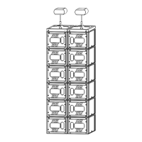
- Pull latch to release the BUMPM10 center link bar, and rotate it upwards
- Pull the bumper front latches, rotate the upper link so that connection points are single leg (GEO M10
Left) or double leg (GEO M10 Right) and release the latches to lock in required position
GEO M10 Left
- Release first GEO M10 link bar, and set AutoRig in automatic lock position
- Position first GEO M10 on top of the bumper, front points will lock automatically
- Connect the bumper link bar (selection from -12° to +12° in 3° steps) to GEO M10 rear rigging plate
(hole marked “bumper”) Lock with the quick release pin BL0820.
GEO M10 Right
- Release first GEO M10 link bar.
- Position first GEO M10 on top of the bumper, and lock it to the bumper with the 2 BL820 quick release
pins.
- Connect the bumper link bar (selection from -12° to +12° in 3° steps) to GEO M10 rear rigging plate
(hole marked “bumper”) Lock with the quick release pin BL0825.
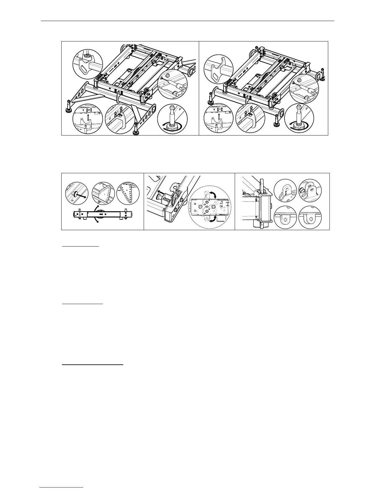
Subsequent GEO M10s
- Position second GEO M10 cabinet with AutoRig
TM
in automatic lock position, and lock front points to
first GEO M10
- Unlock GEO M10 link bar
- Pull the latch to engage the guide in GEO M10 rear slot.
- Adjust the angle by inserting quick release pin BL820 in proper hole.
- Connect subsequent GEO M10 cabinets as with second.
 Loading...