Page 28/79 GEO M10 HARDWARE SETUP PROCEDURE
6.3.2 GEO M10 only on Lightweight Bumper
Required item
- 1 x GMT-LBUMPM10
IMPORTANT
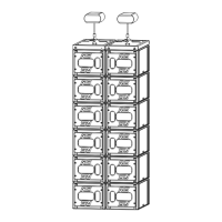
LBUMP10 is rated for a maximum of 3 stacked GEO M10 in any inter cabinet angle
configuration with +/-3° initial angle, provided the stack is assembled according to
below rules:
- LBUMPM10 must always be installed on a horizontal surface
- Public is not allowed within a safety area which radius is equal or higher than assembly
height.
Procedure
GMT-LBUMP10 can be flipped front and back depending if it connects to GEO M10 Right or Left.
- When connecting GEO M10 Left, bumper front is on the “G” hole index side
- When connection GEO M10 Right, bumper front is on the “A” hole index side
GEO M10 Left
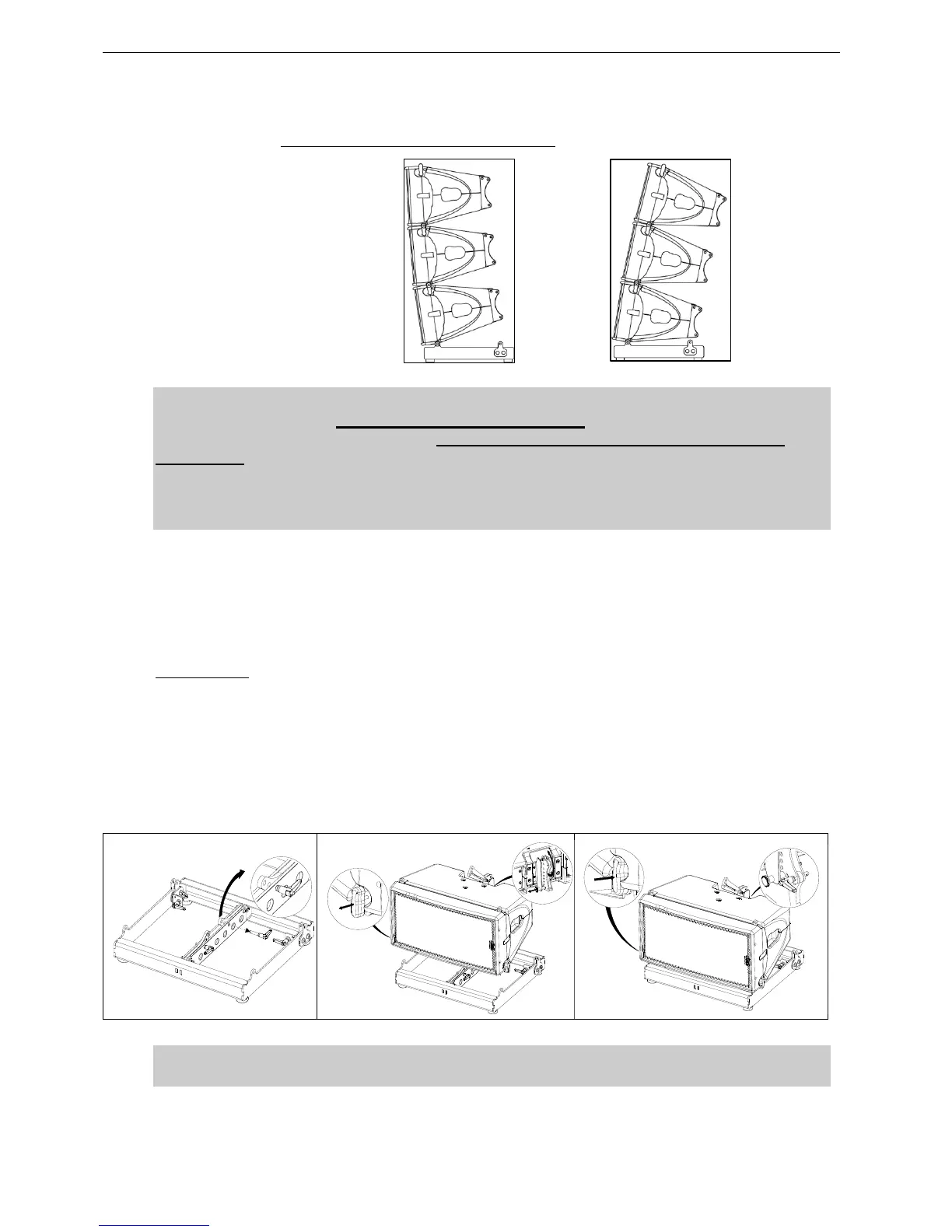
- Set the bumper on the ground so that front is on the “G” hole side
- Remove the BL825 quick release pin of rear LBUMPM10 link bar, and rotate it upwards
- Release first GEO M10 link bar, and set AutoRig in automatic lock position
- Position first GEO M10 on top of the bumper, front points will lock automatically
- Connect the bumper link bar (selection of -3° / 0° / +3°) to GEO M10 rear rigging plate (hole marked
“bumper”) Lock with the quick release pin BL0825.
 Loading...