GEO M10 HARDWARE SETUP PROCEDURE Page 29/79
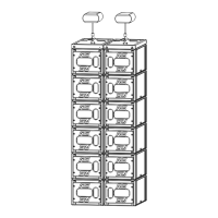
GEO M10 Right
- Set the bumper on the ground so that front is on the “A” hole side
- Remove the two BL820 quick release pins from their side storage position, and the BL825 quick
release pin of rear LBUMPM10 link bar.
- Release GEO M10 link bar.
- Position first GEO M10 on top of the bumper, and lock it to the bumper with the 2 BL820 quick release
pins.
- Connect the bumper link bar (selection of -3° / 0° / +3°) to GEO M10 rear rigging plate (hole marked
“bumper”) Lock with the quick release pin BL0825.
Subsequent GEO M10s
- Position second GEO M10 cabinet with AutoRig
TM
in automatic lock position, and lock front points to
first GEO M10
- Unlock GEO M10 link bar
- Pull the latch to engage the guide in GEO M10 rear slot.
- Adjust the angle by inserting quick release pin BL820 in proper hole.
- Connect subsequent GEO M10 cabinets as with second.
 Loading...