GEO M10 HARDWARE SETUP PROCEDURE Page 35/79
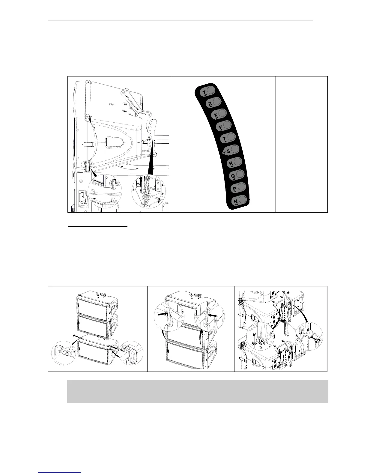
- Release first GEO M10 link bar, and set AutoRig in automatic lock position
- Position first GEO M10 on top of the MNSTKM10, front points will lock automatically
- Connect the MNSTKM10 link bar (selection from -15° to +12° in 3° steps) to GEO M10 rear rigging
plate (hole marked “bumper”) Lock with the quick release pin BL0820.
Y - 15°
Z - 12°
X - 9°
V - 6°
T - 3°
S 0°
R + 3°
Q + 6°
P + 9°
N + 12°
Subsequent GEO M10s
- Position second GEO M10 cabinet with AutoRig
TM
in automatic lock position, and lock front points to
first GEO M10
- Unlock GEO M10 link bar
- Pull the latch to engage the guide in GEO M10 rear slot.
- Adjust the angle by inserting quick release pin BL820 in proper hole.
- Connect subsequent GEO M10 cabinets as with second.
IMPORTANT
Ensure that bumper quick release pins are properly locked into GEO M10, and that all
AutoRig
TM
and rear pins are locked
 Loading...