GEO M10 HARDWARE SETUP PROCEDURE Page 51/79
Procedure
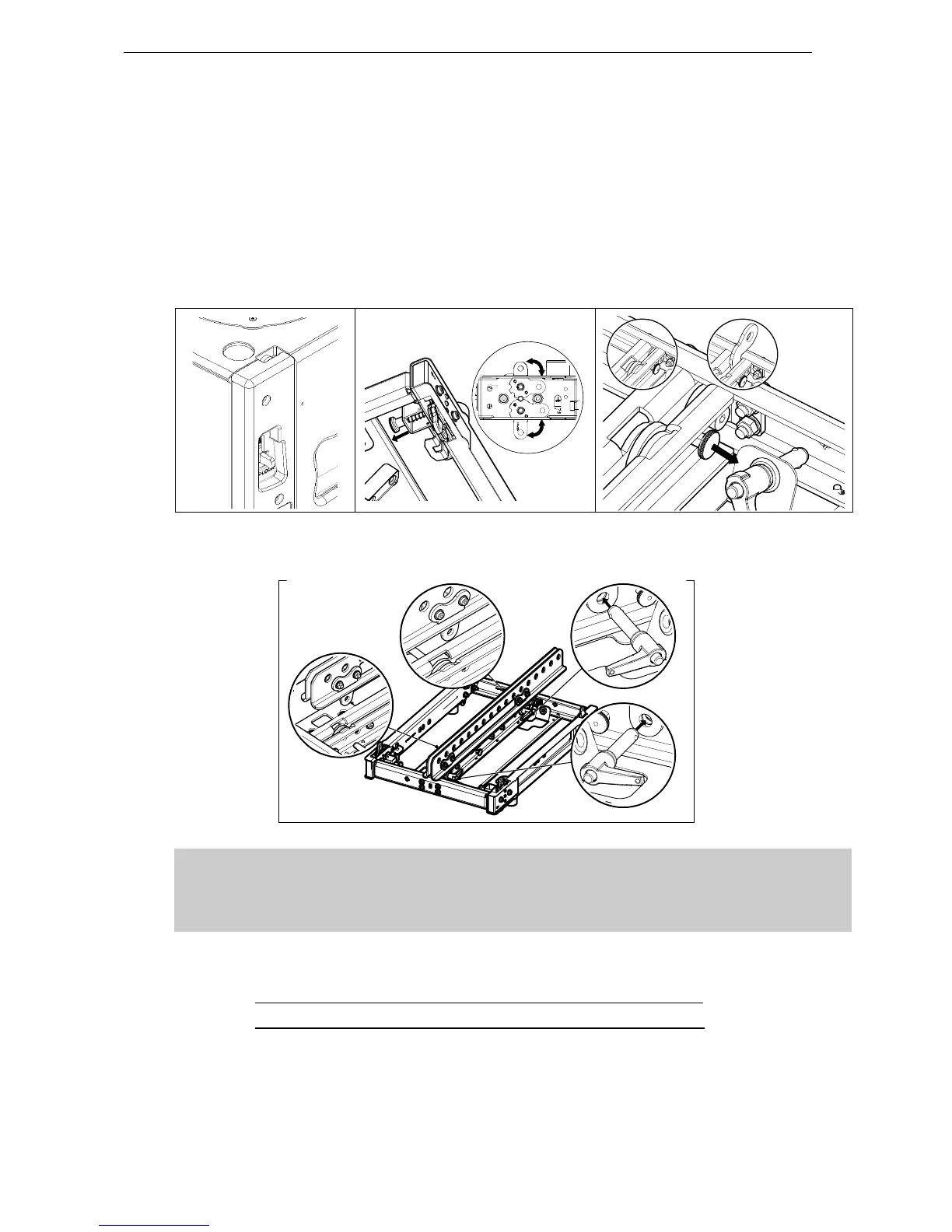
- Position first MSUB15 and unlock front and rear rigging points
- Pull the bumper front latches, rotate the lower links so that connection points are double leg and
release the latches.
- Position bumper on top of first MSUB15 and lock front and rear points to the bumper with 2 BL820
quick release pins.
- If flying with bumper only, pull front and rear center latches, and release front and rear bumper
connecting points.
- If flying from a single point, position VNT-EXBARM10 frontwards or rearwards into NT-BUMPM10
slots and lock devices with the quick release pins 12x40 stored on VNT-BUMPM10.
IMPORTANT
Ensure hoist hook(s) is (are) properly secured to VNT-BUMPM10 or VNT-EXBARM10
shackle(s)
Ensure that all quick release pins are locked
- Insert shackle(s) in bumper or in extension bar in required hole(s), ie:
o If using 1 hoist on VNT-EXBARM10, it must be connected to hole “G”
o VNT-BUMPM10 without extension bar can only be flown with 2 hoists
- Connect hoist hook(s) to shackle(s) and lift assembly to sufficient height in order to connect a second
MSUB15;
 Loading...