Page 22/62 GEO M6 HARDWARE SETUP PROCEDURE
8.2 General Description
GEO M6 modules rigging system 8.2.1
GEO M620 GEO M620Bass
GEO M6BASS and GEO M620 feature a 3 point rigging system, 2 for front connection, and 1 for rear
connection and angle splay settings.
Angle splay setting sequence is: 0.5° - 2° - 5° - 10° - 15° - 20°
Below drawings show rear connecting bar configuration according to “left” or “right” configuration.
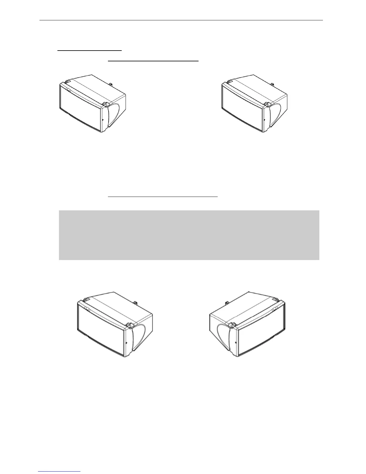
GEO M6 “Left” and “Right” configuration 8.2.2
GEO M6 can be installed “Left” or “Right” :
- “Left” means HF waveguide is left as seen from front
- “Right” means HF waveguide is right as seen from front.
GEO M6 can be connected to bumpers “Left” or “Right” by simply flipping the cabinets.
Whenever possible, NEXO recommends symmetrical designs (preferably NEXO logo
outwards and HF waveguide inwards in stereo configurations)
GEO M620 “Left” Geo M620 “Right”
 Loading...