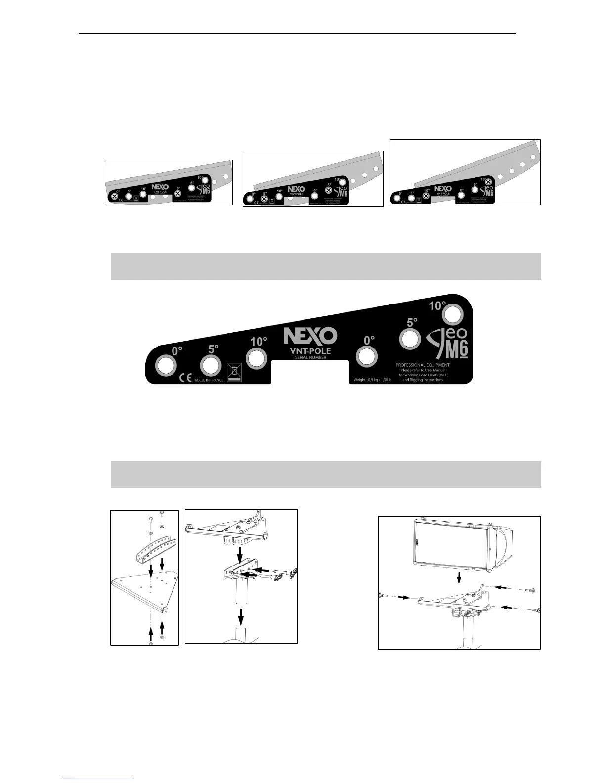
GEO M6 HARDWARE SETUP PROCEDURE Page 31/62
Procedure
- Attach the GMT-LBADPT to the GMT-LBUMPER by using the screws, washers and bolts provided
with GMT-LBDAPT;
- Use the 2 pins provided with VNT-POLE to attach L-BUMP at required vertical angle, according to
below drawings;
Bottom Geo M6 at 0° Bottom Geo M6 at -5° Bottom Geo M6 at -10°
NB: above connection configurations are designed for assembly gravity center being aligned with pole
axis, ensuring maximum safety.
IMPORTANT
Ensure that 8mm pins are properly locked in VNT-POLE
- Connect bottom cabinet to GMT-LBUMP with 3 x VXT-BL515 quick release pins
- Lift assembly on speaker stand or on LS18 with VXT-PLSTD pole stand.
- Connect subsequent cabinets at required inter-angle values with 4 x VXT-BL515 quick release pins
IMPORTANT
Ensure that pins are properly locked into Geo M6
 Loading...