Page 36/62 GEO M6 HARDWARE SETUP PROCEDURE
Procedure with flight case set horizontally
- Open upper cover while the flight case is on its wheels
- Connect GMT-BUMPER to top cabinet 4 x VXT-BL515 quick release pins
- If required, connect GMT-EXBAR to GMT-BUMPER by inserting EXBAR clevis pins into GMT-
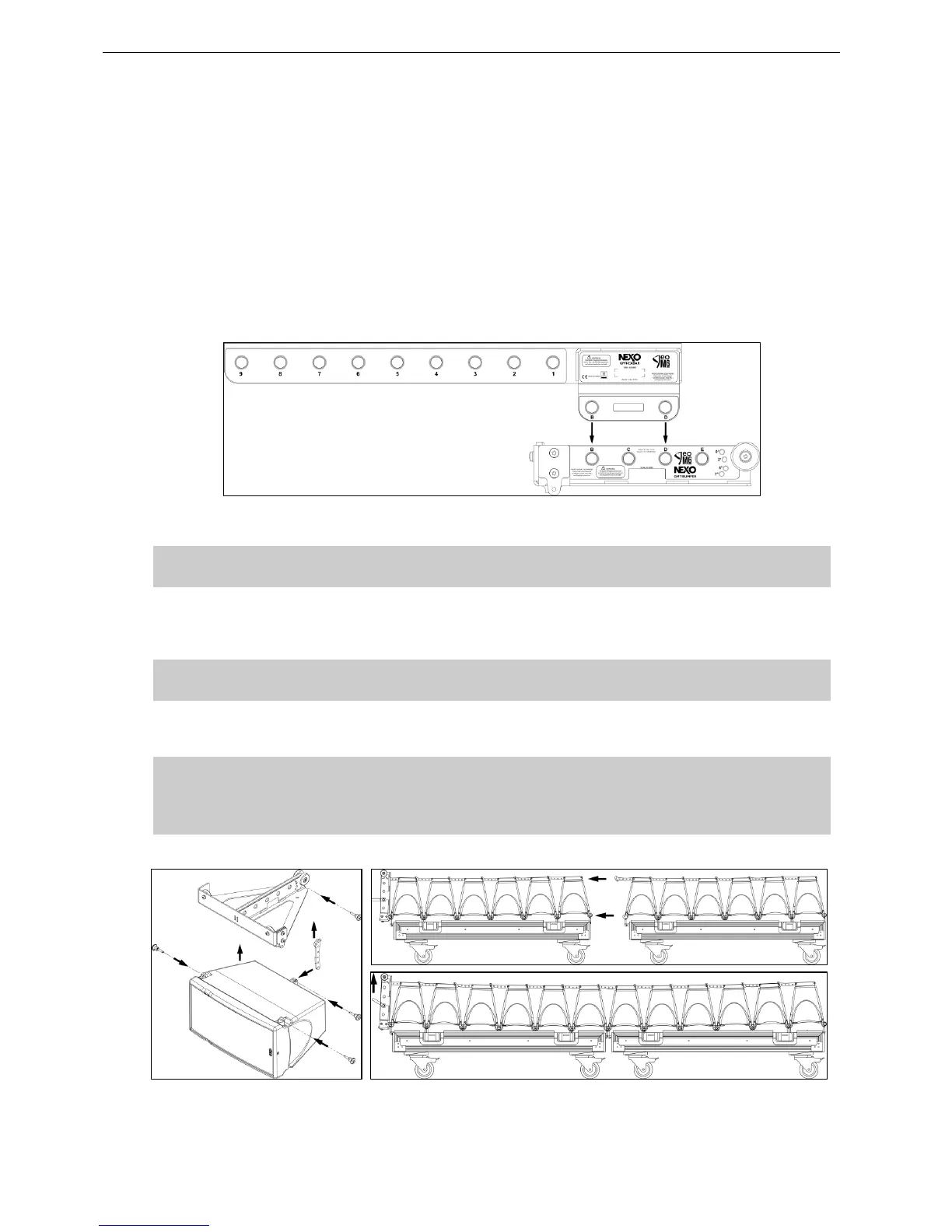
BUMPER “B” and “D” holes
- Connect single hoist to required hole as indicated in NS1 design
o “A”, “B”, “C”, “D” or “E” on GMT-BUMPER
o Or “1” to “9” if using GMT-EXBAR
o If using 2 hoists, connect these using extreme points
(“A” and “E”, or “A” and “9” or “”9” and “E”)
GMT-BUMPER and GMT-EXBAR referenced rigging points
IMPORTANT
Ensure hoist hook(s) is (are) properly secured to GMT-BUMPER
- Start lifting bumper and position angle setting pins at required value as described in section 8.2.3
- Attach second set of 6 x GEO M6 to the first set by bring the second GEO M6 flight case adjacent
to the first one, carry on lifting bumper and set inter-angle values for the second set of GEO M6
IMPORTANT
Ensure all pins are properly locked into Geo M6
- Lift cluster to NS-1 defined rigging height, secure cluster horizontally to prevent it from rotating
- Secure bumper with secondary safety steel.
IMPORTANT
The requirements for secondary safety systems vary with territories. However, the
secondary safety steel MUST have a SWL equivalent or greater than that of the rigging
system.
 Loading...