NXAMP4x1
54
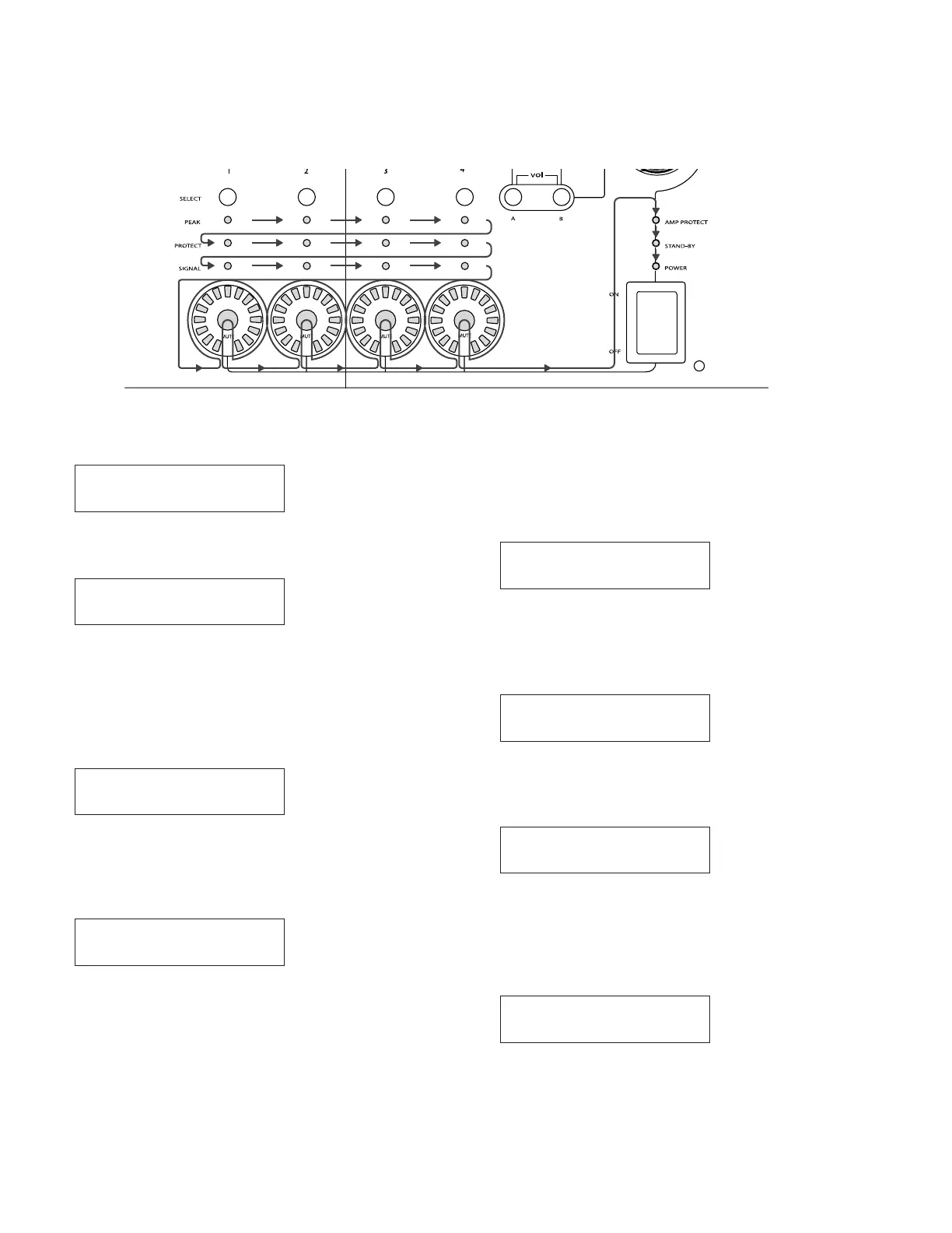
Lighting order
00 CHOOSE TEST < >
04 LCD
4-4. LCD test
Press the [B] button to start the test.
First the following display appears.
04 LCD
All the dots of the LCD go on and off two times. Finally, all
the dots of the LCD are lit. Confirm that all the dots of the
LCD have lit normally. If OK, press the [B] button to re-
turn the display to the test menu screen.
4-5. RS-232C test
00 CHOOSE TEST < >
05 RS-232C
Connect the RS-232C jig to the R232C port of the
NXAMP4x1.
Then press the [B] button to start the test, and the follow-
ing display appears.
05 RS-232C
RS-232C OK ?
Press the [B] button to continue the test. The test executes
automatically.
After executing the test, the following display appears.
(When an error occurs, the “ERROR” appears and the
test program is stopped.)
05 RS-232C
RELEASE RS-232C
Disconnect the RS-232C jig from the RC232C port. Press
the [B] button to return the display to the test menu screen.
4-6. GPI test
00 CHOOSE TEST < >
06 GPI
Connect the GPI jig to the GPIO port of the NXAMP4x1.
Then press the [B] button to start the test, and the follow-
ing display appears.
06 GPI
GPO[0:4] TEST OK ?
Switch the GPI jig to the GPO [0:4] position and press
the [B] button to continue the test.
The test executes automatically.
If normal, the following display appears. (If an error oc-
curs, “ERROR” appears and the test program is stopped.)
06 GPI
GPO[5:7] TEST OK ?

 Loading...


