NXAMP4x1
61
4. Inspection with analog test mode
Condition:
• Perform each test item in this section with the analog test mode of the test program. (See page 57)
• Unless otherwise specified, perform the test with a 8 Ω resistor is connected to each output terminal.
4-1. Link out
Input the 1 kHz, -10 dBu sine wave to each input terminal and confirm that the output voltage obtained at each link out terminal
is -10 ± 0.5 dBu.
4-2. Efficiency
Input the 1 kHz sine wave to the channel 1 input terminal and confirm that the primary power consumption is 175 ± 10 W when
the output voltage obtained at the channel 1 output terminal is +29.2 dBu.
Perform the same test for channels 2-4 in the same manner.
4-3. Gain
Input the 1 kHz, 0 dBu sine wave to each input terminal and confirm that the output voltage obtained at each output terminal
is +29.1 ± 1.2 dBu.
4-4. Frequency response
Perform the following test at each channel.
Input the 10 Hz, 1 kHz, 20 kHz, 0 dBu sine wave to the input terminal and one by one measure the output voltage obtained at
the output terminal for each frequency.
Confirm that the output voltage at 10 Hz is 0 ± 0.5 dB when compared with the output voltage at 1 kHz (0 dB).
Confirm that the output voltage at 20 kHz is +0.5 ± 0.5 dB when compared with the output voltage at 1 kHz (0 dB).
4-5. Distortion
Input the 1kHz sine wave to each channel input terminal and confirm that the distortion in each channel output terminal is 1.0
% or less when 500 W (with 8 ohms load) output is obtained for each terminal at the same time.
4-6. Maximum output
Connect the 4 ohms 500 W resistor to each output terminal.
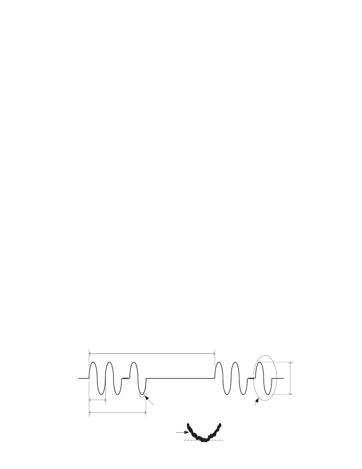
Input the BURST signal as shown in fig. 2 to each input terminal and adjust the input signal level so that a Vburst voltage of 174
Vp-p (volt peak to peak) is obtained in each channel output terminals.
Measure the last wave of the BURST signal peak to peak by the oscilloscope's MEASURE function. Confirm that the mea-
sured voltage is 170 volt or more. (See fig. 2)
Note: Perform the test of all channels at the same time.
Fig. 2
The last one wave of burst signal
shall be measured.
Close-up
The center of the emission line shall
be adopted as the measurement value.
Signal
20 msec
1 msec
500 msec
Vburst
Cursor
 Loading...


