GENERAL DESCRIPTION
the two converters work in opposite phase, some noise is cancelled; this is preferable for
both sound quality and EMC (Electro magnetic compatibility).
Analog Input block
After linking the two XLRs for each channel, the analog input block has an EMC filter and a
precision input buffer that will remove the common noise on the input signal. The
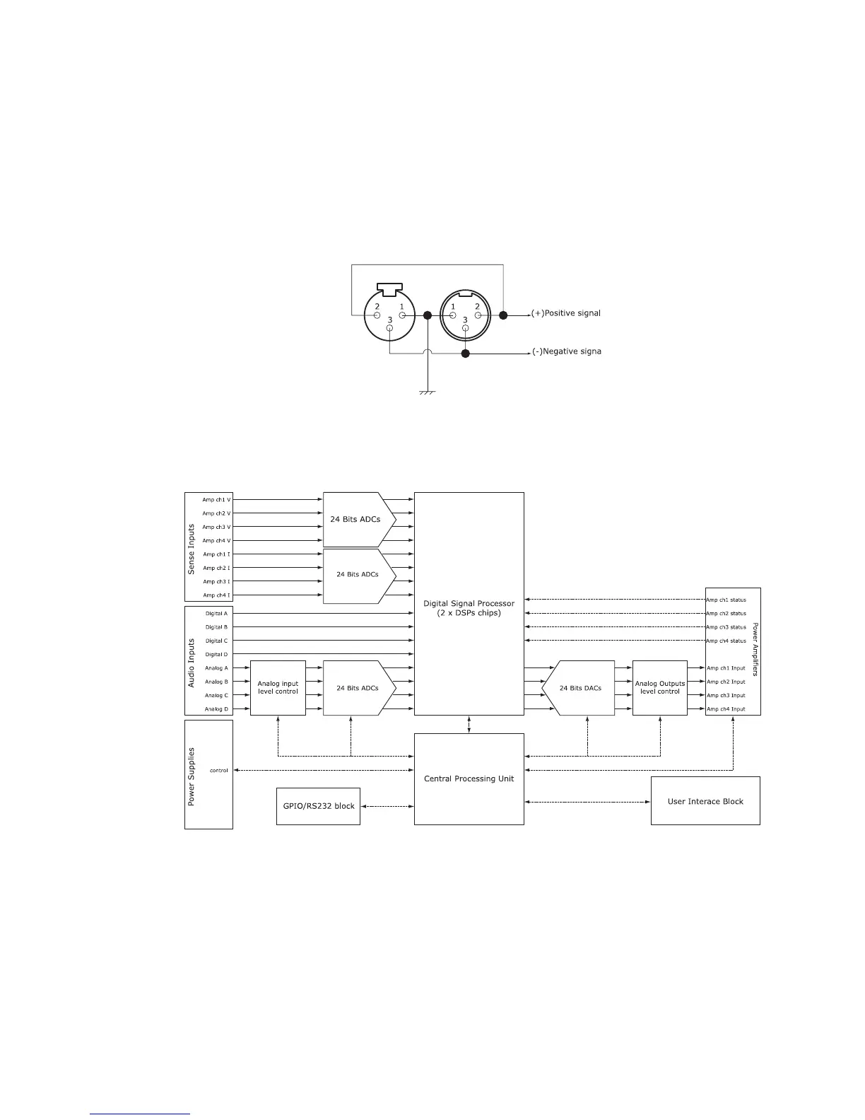
maximum level allowed for the input signal is + 28 dBU (55 Volts peak to peak). The pin
out of the input XLR is given bellow.
Control block
The control block contains several sub-block that are detailed bellow.
The plain lines show the audio or sense signal (sense are voltage or current signal
measured at the output of each amplifier). The dashed lines show the digital
communication signal among several block.
You can see the audio input on the left; there are four analog inputs (from input XLR)
named Analog A, Analog B and so on… and four digital inputs (Digital A, Digital B and so
on…) from the expansion slot. These eight signals can be patched inside the DSP to any
channel of processing/amplifying (see further for a block diagram of what is inside the
PAGE 25 OF 80

 Loading...


