16
Right Speaker
Control
Common
Left Speaker
+
-
+
-
+
+
C-6 Zone Out
In
Out
Keypad
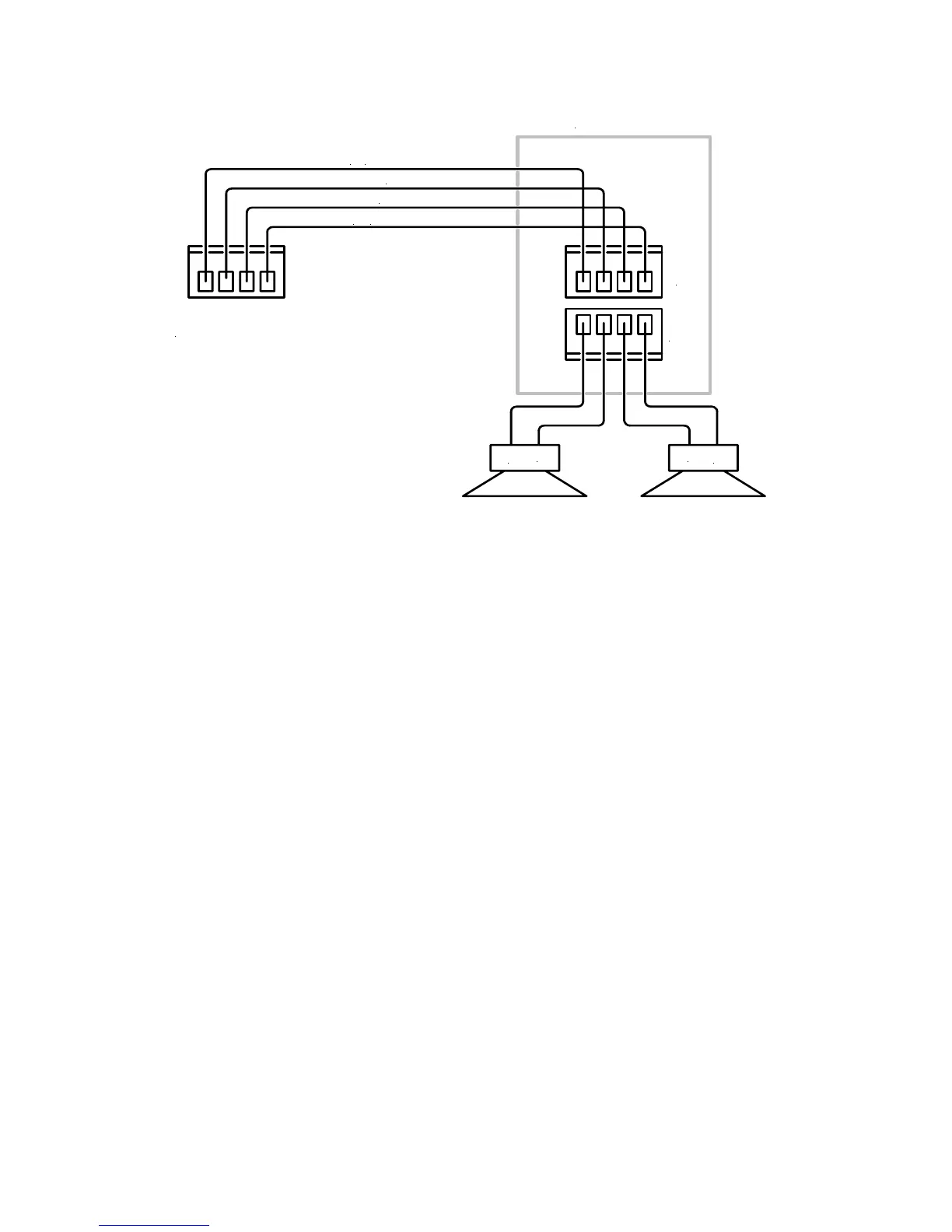
Figure 12. Typical Zone Keypad Wiring
ZONE CONNECTIONS AND SETUP
Keypads
As described in the section on Wiring, the Speaker/Keypad Terminals are specially configured for
Phantom Control that combines speaker level audio signals, keypad control signals and power for
the keypads all on the same wire. Special care must be used in making the Speaker/Keypad
connections.
1. Using four conductor stranded wire, strip approximately ¼” of insulation from each conductor.
Twist the strands until tight.
2. Connect the bare wires to the plug-in four terminal screw connectors included with the C-6
accessories. Be sure to maintain proper polarity on the LEFT+, CONTROL, COMMON and
RIGHT+ terminals for each zone output. Be sure there are no loose strands sticking out that
could cause a short.
3. Plug connector into the Speaker/Keypad Input terminal on the back of the Keypad. Repeat for
all zones.
Speakers
The Speaker Output Terminals output speaker level audio only and use a standard speaker
connection configuration.
1. Using two conductor stranded wire, strip approximately ¼” of insulation from each conductor.
Twist the strands until tight.
2. Connect the bare wires to the plug-in four terminal screw connectors included with the C-6
accessories. Be sure to maintain proper polarity from the L+, L-, R- and R+ terminals for each
speaker pair output. Be sure there are no loose strands sticking out that could cause a short.
3. Plug connector into the Speaker Output terminal on the back of the Keypad. Repeat for all
zones.
Video
Connect the RG6 quad shield coax to a composite video input on the TV or video display. Repeat
for all zones.