15
on the Trigger output when connecting to the device to be switched. Be sure there are no loose
strands sticking out that could cause a short.
Feature Buss
The Feature Buss is an RJ45 jack that is currently inactive. It will be utilized to provide additional
control flexibility in the future. Periodically visit www.nexusaudiosystems.com
for updates.
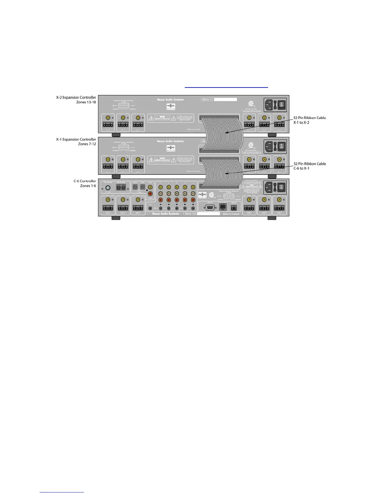
Figure 11. C-6 Expanded System
Multiple C-6 Controllers
The Nexus C-6 System is expandable to up to 18 Zones. There are two Expansion Controllers
that are used for expansion. The X-1 expands a C-6 system for zones 7-12 and the X-2 expands
the system for zones 13-18.
Audio, Video and Control signals as well as System information such as ‘Group’ data are all
transmitted via a 52 pin ribbon cable making expansion easy without having to make additional
A/V and control connections.
Once programming and setup have been done in the C-6 Controller for Tuner setup, IR
commands, Source Naming and Input Trim they become universal to the system regardless of
the number of zones. The only additional steps required when adding Expansion Controllers are
Zone Naming, and configuring the added zones for Zone Mute and Paging.
Expanding Zones 7-12
Connect one end of the 52 pin ribbon cable included with the X-1 Expansion Controller to the
LOWER 50 pin Expansion Buss Port on the X-1. Connect the other end of the ribbon cable to the
Expansion Buss Port on the C-6 Controller. Make Keypad/Speaker connections and Video
connections as described in ZONE CONNECTIONS AND SETUP below.
Expanding Zones 13-18
Connect one end of the 52 pin ribbon cable included with the X-2 Expansion Controller to the
UPPER 50 pin Expansion Buss Port on the X-1. Connect the other end of the ribbon cable to the
Expansion Buss Port on the X-2 Controller. Make Keypad/Speaker connections and Video
connections as described in ZONE CONNECTIONS AND SETUP below.