NI cDAQ-9178/9174 User Guide and Specifications 38 ni.com
Implicit Buffered Pulse Measurement
In an implicit buffered pulse measurement, on each edge of the Gate signal, the counter stores the count
in the FIFO. The USB-STC3 transfers the sampled values to host memory using a high-speed data
stream.
The counter begins counting when it is armed. The arm usually occurs between edges on the Gate input
but the counting does not start until the desired edge. You can select whether to read the high pulse or
low pulse first using the StartingEdge property in NI-DAQmx.
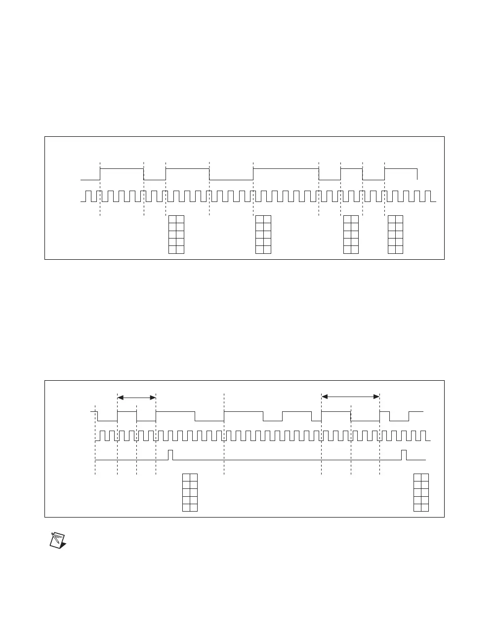
Figure 28 shows an example of an implicit buffered pulse measurement.
Figure 28. Implicit Buffered Pulse Measurement
Sample Clocked Buffered Pulse Measurement
A sample clocked buffered pulse measurement is similar to single pulse measurement, but a buffered
pulse measurement takes measurements over multiple pulses correlated to a sample clock.
The counter performs a pulse measurement on the Gate. On each sample clock edge, the counter stores
the high and low ticks in the FIFO of the last pulse to complete. The USB-STC3 transfers the sampled
values to host memory using a high-speed data stream.
Figure 29 shows an example of a sample clocked buffered pulse measurement.
Figure 29. Sample Clocked Buffered Pulse Measurement
Note If a pulse does not occur between sample clocks, an overrun error occurs.
For information about connecting counter signals, refer to the Default Counter/Timer Routing section.
Counter
Armed
Gate
Source
HL
42
HL
4
2
44
6
2
2
2
HL
4
2
4
4
6
2
HL
42
4
4
Buffer
Co
unter
Armed
Gate
Source
HL
2
2
HL
22
3
3
Sample
Clock
S1
S2
Buffer
2
2
33