© National Instruments Corporation 37 NI cDAQ-9178/9174 User Guide and Specifications
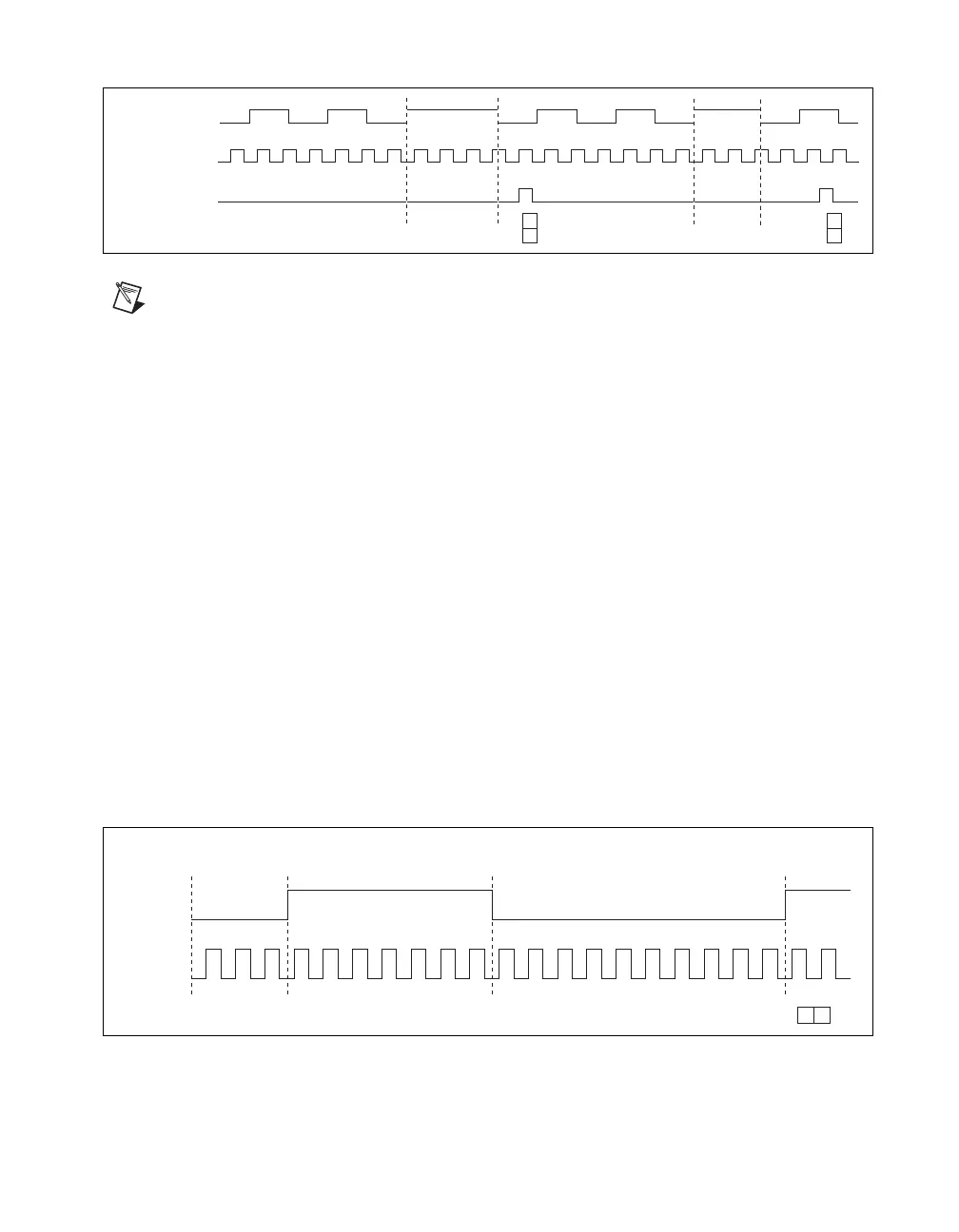
Figure 26 shows an example of a sample clocked buffered pulse-width measurement.
Figure 26. Sample Clocked Buffered Pulse-Width Measurement
Note If a pulse does not occur between sample clocks, an overrun error occurs.
For information about connecting counter signals, refer to the Default Counter/Timer Routing section.
Pulse Measurement
In pulse measurements, the counter measures the high and low time of a pulse on its Gate input signal
after the counter is armed. A pulse is defined in terms of its high and low time, high and low ticks or
frequency and duty cycle. This is similar to the pulse-width measurement, except that the inactive pulse
is measured as well.
You can route an internal or external periodic clock signal (with a known period) to the Source input of
the counter. The counter counts the number of rising (or falling) edges occurring on the Source input
between two edges of the Gate signal.
You can calculate the high and low time of the Gate input by multiplying the period of the Source signal
by the number of edges returned by the counter.
Refer to the following sections for more information about NI cDAQ-9178/9174 pulse measurement
options:
• Single Pulse Measurement
• Implicit Buffered Pulse Measurement
• Sample Clocked Buffered Pulse Measurement
Single Pulse Measurement
Single (on-demand) pulse measurement is equivalent to two single pulse-width measurements on the
high (H) and low (L) ticks of a pulse, as shown in Figure 27.
Figure 27. Single (On-Demand) Pulse Measurement
Pulse
Source
Sample Clock
2 342
4
3
22
4
Buffer
Counter
Armed
Gate
Source
HL
710
7
10
Latched
Value
987654321564321