NI cDAQ-9178/9174 User Guide and Specifications 42 ni.com
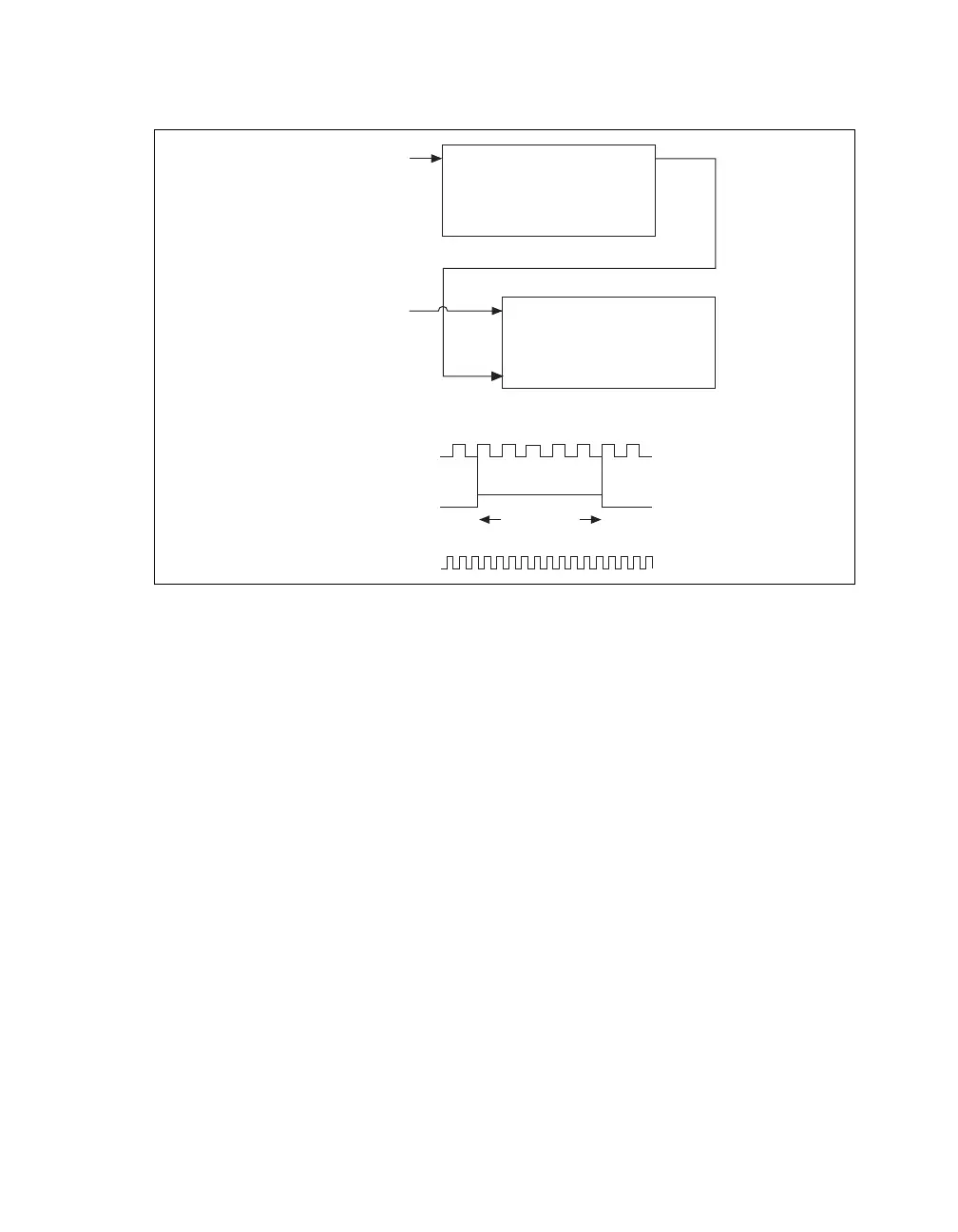
You can route the signal to measure to the Source input of Counter 0, as shown in Figure 33. Assume
this signal to measure has frequency fx. NI-DAQmx automatically configures Counter 0 to generate a
single pulse that is the width of N periods of the source input signal.
Figure 33. Large Range of Frequencies with Two Counters
Next, route the Counter 0 Internal Output signal to the Gate input of Counter 1. You can route a signal
of known frequency (fk) to the Counter 1 Source input. Configure Counter 1 to perform a single
pulse-width measurement. Suppose the result is that the pulse width is J periods of the fk clock.
From Counter 0, the length of the pulse is N/fx. From Counter 1, the length of the same pulse is J/fk.
Therefore, the frequency of fx is given by fx = fk *(N/J).
Sample Clocked Buffered Frequency Measurement
Sample clocked buffered point frequency measurements can either be a single frequency measurement
or an average between sample clocks. Use CI.Freq.EnableAveraging to set the behavior. For buffered
frequency, the default is True.
A sample clocked buffered frequency measurement with CI.Freq.EnableAveraging set to True uses
the embedded counter and a sample clock to perform a frequency measurement. For each sample clock
period, the embedded counter counts the signal to measure (fx) and the primary counter counts the
internal time-base of a known frequency (fk). Suppose T1 is the number of ticks of the unknown signal
counted between sample clocks and T2 is the number of ticks counted of the known timebase as shown
in Figure 34. The frequency measured is:
fx = fk * (T1/T2)
Source Out
Counter 0
Source
Gare
Out
Counter 1
Signal to
Measure (fx)
Signal of Known
Frequency (fk)
CTR_0_SOURCE
(Signal to Measure)
CTR_0_OUT
(CTR_1_GATE)
CTR_1_SOURCE
Interval
to Measure
0123 … N