Part Number 12762 Rev 1.1 | April 30, 2014 MOUNTING
Removing and Replacing the Cover
10 NETWORK CONTROLLER 3E & 6E MOUNTING AND WIRING GUIDE |
Step 2 Position the controller on the rail, tilting to hook DIN rail tabs over one
edge of the DIN rail (Figure 1).
Step 3 Use a screwdriver to pry down the plastic locking clip, and push down and
in on the unit, forcing the locking clip to snap over the other DIN rail edge.
Step 4 Mount any accessory module (I/O module, NPB-PWR) onto the DIN rail in
the same manner.
Step 5 Slide the accessory module along the DIN rail to connect its 20-position
plug into the controller.
Step 6 Repeat this for all accessories, until all are mounted on the DIN rail and
firmly connected to each other.
Step 7 To keep the final assembly together, secure at both ends with DIN rail
end-clips provided by the DIN rail vendor. This also prevents the assembly
from sliding on the DIN rail. See Figure 1.
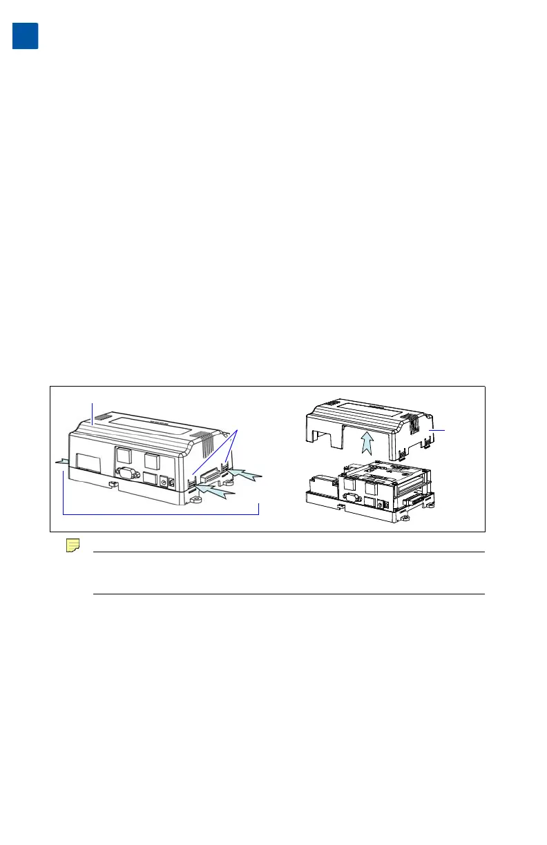
Removing and Replacing the Cover
You must remove the controller’s cover to install any option cards, or to install (or
replace) the optional NiMH backup battery. The cover snaps onto the base with four
plastic end tabs—two on each end.
Figure 2 Press in four tabs on ends of cover to remove.
Note If accessory modules are plugged into the controller, you may need to slide
them away from the unit to get to the end cover tabs.
• To remove the cover, press in the tabs on both ends of the unit, and carefully lift it off.
• To replace the cover, orient it so the cutout area for comm ports is correct, then
push inwards to snap in place.
Board Layout
Figure 3 shows the location of LEDs, option slots, and other features of the T-300E
or T-600E controller with cover removed. For a side view of communications ports
and other features, see Figure 6 on page 18.
Cover
Press
Tabs In
Cover Tabs
(2 each end)
Cover
lifted
away