ABOUT EXPANSION OPTIONS Part Number 12762 Rev 1.1 | April 30, 2014
About Accessory Modules
| NETWORK CONTROLLER 3E & 6E MOUNTING AND WIRING GUIDE 13
Note If you are also installing the optional NiMH battery/bracket assembly now,
remove and retain the other two screws, that is for the other option slot.
Step 6 Carefully insert the pins of the option card into the socket headers of the
option card slot.
The mounting holes on the option board should line up with the standoffs
on the base board. If they do not, the connector is not properly aligned.
Press until the option card is completely seated.
Step 7 Place the custom end plate for the option card over the connector(s) of the
option card. With some option cards, the card’s end plate is pre-fastened.
Step 8 If installing (or replacing) the optional NiMH battery/bracket assembly:
a Plug the battery connector plug into the battery connector on the control-
ler’s base board.
b Set the battery and bracket assembly over the option card slots, with the
mounting holes aligned with the standoffs.
c Place the four screws through the bracket, end plates, and into the standoffs
on the controller base board. With a screwdriver, hand tighten the screws.
For more details, see
“NiMH Battery Installation and Maintenance,”
page 26.
Otherwise, place the two screws through the option card end plate and into
the standoffs on the base board.
With a screwdriver, hand tighten the screws.
Step 9 Replace the cover on the controller.
Step 10 Restore power to the controller and verify normal operation.
About Accessory Modules
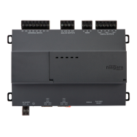
The controller has a 20-pin, right-angle, Euro-DIN connector that accepts
custom-built accessory modules. The connector provides power and signal lines to
any connected modules.
Warning • Power to the controller must be OFF when inserting or unplugging
accessory modules. Wait for all LED activity to stop (all LEDs off).
• Also, do not connect live voltages to the inputs or outputs of an I/O
module while it is in an “un-powered state” before plugging the
module into the controller.
Otherwise,
damage to the I/O module and/or controller may result
!
Each accessory module has a DIN-mount base, and typically provides two (2) 20-pin
connectors that allow you to “chain” multiple accessories. Tab le 2 lists the currently
available modules.