Part Number 12762 Rev 1.1 | April 30, 2014 WIRING DETAILS
About Accessory Modules
14 NETWORK CONTROLLER 3E & 6E MOUNTING AND WIRING GUIDE |
Wiring Details
See Figure 3 on page 11 to locate connectors and components on the controller.
Make connections to the controller in the following order.
1 Install any option card (LON, RS-485, RS-232, etc.) in the available option slots.
See “Installing an Option Card,” page 12 for a procedure. For complete details,
refer to the document that shipped with the option card.
If installing the optional NiMH battery, do that after inserting option card(s). See
“NiMH Battery Installation and Maintenance,” page 26.
2 Connect supplied grounding wire from the earth ground lug on the controller, as
well ground wire for each accessory module, to a nearby earth grounding point.
See “Grounding,” page 15.
3 Prepare power wiring (leave unit powered off ). See “Power Wiring,” page 15.
4 Connect communications cables. See “Communications Wiring,” page 18 for
ports on the controller. For ports on any installed option card (485-PWR, LON,
RS-485, modem) see the option’s specific mounting and wiring guide for details.
5 If I/O accessory modules are installed, connect I/O wiring. Refer to the appropri-
ate mounting and wiring guide for details.
6 Apply power to the unit. See “Power Up and Initial Checkout,” page 23.
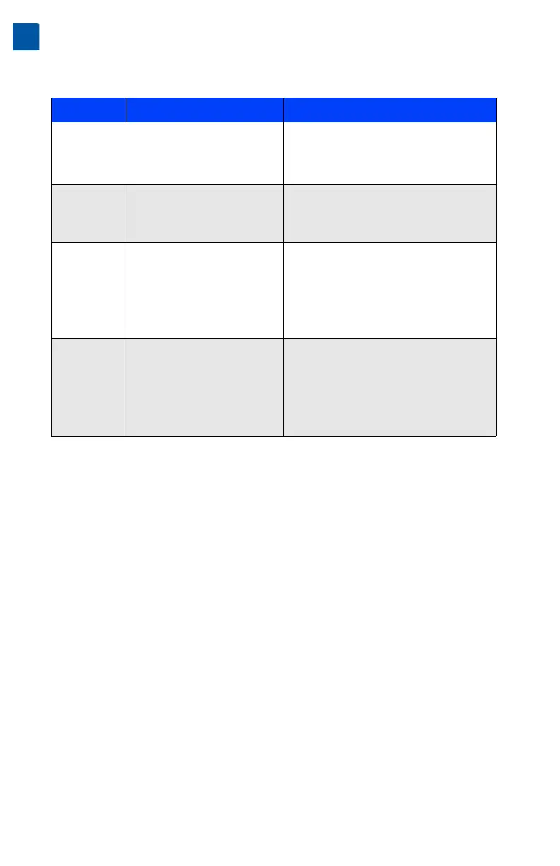
Table 2 Accessory modules
a
compatible with the T-300E and T-600E controller.
a. A wall mount AC adapter (WPM-XXX) is also available; however, it is not an accessory module that
mounts on the 20-pin connector of the controller.
Model Description Notes
NPB-PWR DIN-mountable, 24V isolated
power module, used to power
the controller from a dedicated,
external, Class-2, 24Vac trans-
former or a 24Vdc power supply.
Only one NPB-PWR per controller.
• Do not install if using WPM-
XXX
or
NPB-PWR-UN.
• For wiring, see “NPB-PWR,” page 15.
NPB-PWR-UN DIN-mountable, Universal
120–240Vac input, 15Vdc output,
30W power supply to power the
controller.
Only one NPB-PWR-UN per controller.
• Do not install if using WPM-
XXX
or
NPB-PWR.
• For wiring, see “NPB-PWR-UN,” page 16.
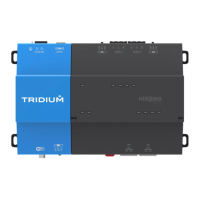
T-IO-16 DIN-mountable, 16 points I/O
module, used to provide I/O
points as noted.
Up to four (maximum) T-IO-16 modules are
supported. Each provides these I/O points:
• 8 - Universal Inputs (UIs).
• 4 - Digital Outputs (DOs), SPST-relay type.
• 4 - Analog Outputs (AOs), 0–10Vdc type.
Wiring is covered in the
T-IO-16 Installation
and Configuration Guide
.
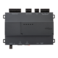
T-IO-34 DIN-mountable, combined 34
points I/O with 24V isolated
power module, used to provide
I/O points as well as power the
controller from a dedicated,
external, Class-2, 24Vac trans-
former or a 24Vdc power supply.
Only one T-IO-34 module per controller.
This module provides these I/O points:
• 16 - Universal Inputs (UIs).
• 10 - Digital Outputs (DOs), SPST-relay type.
• 8 - Analog Outputs (AOs), 0–10Vdc type.
Wiring is covered in the
T-IO-34 Installation
and Configuration Guide
.