Part Number 12762 Rev 1.1 | April 30, 2014 WIRING DETAILS
RS-485 Biasing
20 NETWORK CONTROLLER 3E & 6E MOUNTING AND WIRING GUIDE |
RS-485 Biasing
The RS-485 port on the controller’s base board has a pair of two-pin jumpers that
can be shorted with jumper blocks to provide “biasing”. As shipped from the factory,
these pins are not shorted, thus the RS-485 port is unbiased.
Note See “Need for RS-485 Bias” before following the “Adding RS-485 Bias”
procedure. In many cases, the default unbiased RS-485 port is preferred.
Need for RS-485 Bias
Note A full discussion of communication line termination is beyond the scope of
this document.
Biasing sometimes improves RS-485 communications by eliminating
“indeterminate” idle states. When you install two, 2-pin shorting blocks on the
controller’s RS-485 bias jumper pins, this adds two onboard 3.3K ohm resistors into
the controller’s RS-485 circuit, as follows:
• from RS-485 “+” to 5V.
• from RS-485 “-” to Ground.
Note
• In general,
only one device
on an RS-485 trunk should be biased. Other-
wise, undue loading of the circuit may result, with fewer devices supported.
• RS-485 bias resistors are different than “termination resistors”, exter-
nally installed at the two physical ends of a daisy-chained RS-485 trunk,
across the “+” and “–” terminals. Termination resistors are typically 100
or 120 ohm value resistors.
• Whenever termination resistors are used, RS-485 biasing is typi-
cally required.
Adding RS-485 Bias
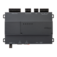
To add biasing, you must power off the controller and remove a few assemblies (such
as metal shield and NPM3E or NPM6E processor module) to access the base board
jumper pins, located behind the RS-485 port. Then you must reposition the two
shorting blocks on these jumper pins. Then you reassemble the unit by remounting
the processor module, hex standoffs, metal shield, and shield screws.
Warning Remove all power from the controller before working on the unit.
Observe static discharge precautions. See the “Static Discharge Pre-
cautions” section on page 6.
If the controller is already installed or mounted, it is recommended that you remove
it first. Then work on a flat, stable, well-lit work surface.