WIRING DETAILS Part Number 12762 Rev 1.1 | April 30, 2014
RS-485 Biasing
| NETWORK CONTROLLER 3E & 6E MOUNTING AND WIRING GUIDE 21
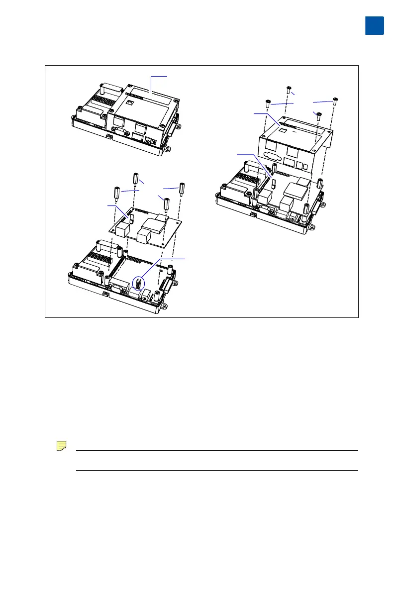
Figure 7 Basic stages of controller disassembly.
Procedure 4 Disassembling the controller.
Step 1 Remove all power from the controller. (See previous Warning).
Step 2 Remove the plastic cover. See “Removing and Replacing the Cover,” page 10.
Step 3 Remove the four Phillips head screws that secure the metal shield, and set
them aside.
Step 4 Remove the metal shield and set it aside.
To do this, carefully pry up from the top (hole vented side) first, then push
out the other side to slip the port holes past the port edges. Then lift the
shield up and away.
Note Be mindful of the “side clips” on the controller’s two Ethernet ports.
Step 5 Use a 1/4" (7mm) nutdriver to unscrew the four metal standoffs, and set
them aside.
Step 6 Carefully pry up the NPM3E or NPM6E processor module board, noting
that the two-row, 50-pin connector is on the option card side. Keep the
board level as you work it loose from this connector.
Step 7 Set the processor module board aside. Note the jumper block on the base
board behind the RS-485 port (see bottom of Figure 7).
Phillips
head
screws
Metal
standoffs
Metal shield
lifted away
Cover removed,
reveals metal shield
NPM3E or NPM6E
Processor module
(board)
Processor module
lifted away
Jumper block for
RS-485 biasing
1
2
3
 Loading...