Part Number 12762 Rev 1.1 | April 30, 2014 WIRING DETAILS
RS-485 Biasing
22 NETWORK CONTROLLER 3E & 6E MOUNTING AND WIRING GUIDE |
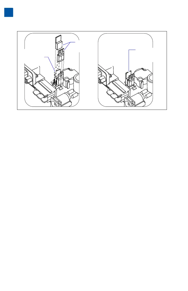
Figure 8 Install shorting blocks across both sides of jumper block to add RS-485 bias.
Procedure 5 Installing shorting blocks to add RS-485 biasing.
Step 1 Locate the four jumper pins behind the RS-485 port, with 2-pin shorting
blocks installed on one pin each. See Figure 8.
Step 2 To add biasing, remove and replace both shorting blocks back onto the
jumper pins, as shown in Figure 8 (right).
Procedure 6 Reassembling the controller.
Step 1 Carefully replace the processor module board onto the 50-pin connector,
with its corner mounting holes aligned on the four lower standoffs. Press
down on the connector to fully seat the board. See Figure 7 on page 21.
Step 2 Refasten the four metal hex standoffs, hand tightening with a 1/4” (7mm)
nutdriver.
Step 3 Replace the shield back onto the unit. To do this, carefully ease it over the
port side first, then spring it down over the other side. Make sure that its
corner holes align with the metal standoffs below.
Step 4 Refasten the four Phillips head screws that secure the shield to the stand-
offs.
Step 5 Replace the plastic cover onto the unit.
Position of
pre-installed
shorting blocks
(no biasing)
Shorting blocks
installed across
jumper pins
(biasing added)
Shorting
blocks lifted
away