WIRING DETAILS Part Number 12762 Rev 1.1 | April 30, 2014
Communications Wiring
| NETWORK CONTROLLER 3E & 6E MOUNTING AND WIRING GUIDE 19
Serial
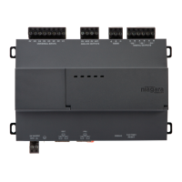
There are two “RS” serial ports on the controller’s base board. Each has a UART
capable of operation up to 115,200 baud. At the bottom of the board (see Figure 6) is
an RS-232 port using an DB-9 plug (male) connector. To the right of this is a
two-wire plus shield RS-485 port, using a 3-position screw-terminal connector plug.
Note A green “receive” LED and yellow “transmit” LED are provided for both
serial ports. These LEDs are on the controller’s bottom board, on the side
opposite to the serial connectors (see Figure 3 on page 11). These LEDs are
labeled on the board (COM1, COM2) and are not visible with the cover on.
RS-232
An RS-232 serial port using a male DB-9 connector always operates as COM1. You
can use standard DB-9 serial cables with this port.
The controller is a serial DTE device, such that another DTE device (PC, for example)
requires a “null modem” cable. If connecting to a DCE device such as a modem, use a
straight-through cable.
Tabl e 3
provides standard serial DB-9 pinouts.
Note If rebooted with the mode jumper in the “Serial Shell” position (see Figure
3 on page 11), the RS-232 port provides “system shell” access. See the JACE
NiagaraAX Install and Startup Guide for related details.
.
RS-485
An RS-485 port uses a 3-position, screw terminal connector, and always operates as
COM2. As shown in the Table 3 pinouts, from left-to-right the screw terminals are
shield (S), plus (+), and minus (–). Wire in a continuous multidrop fashion to other
RS-485 devices, meaning “minus to minus”, “plus to plus,” and “shield to shield.”
Connect the shield to earth ground at one end only, such as at the controller.
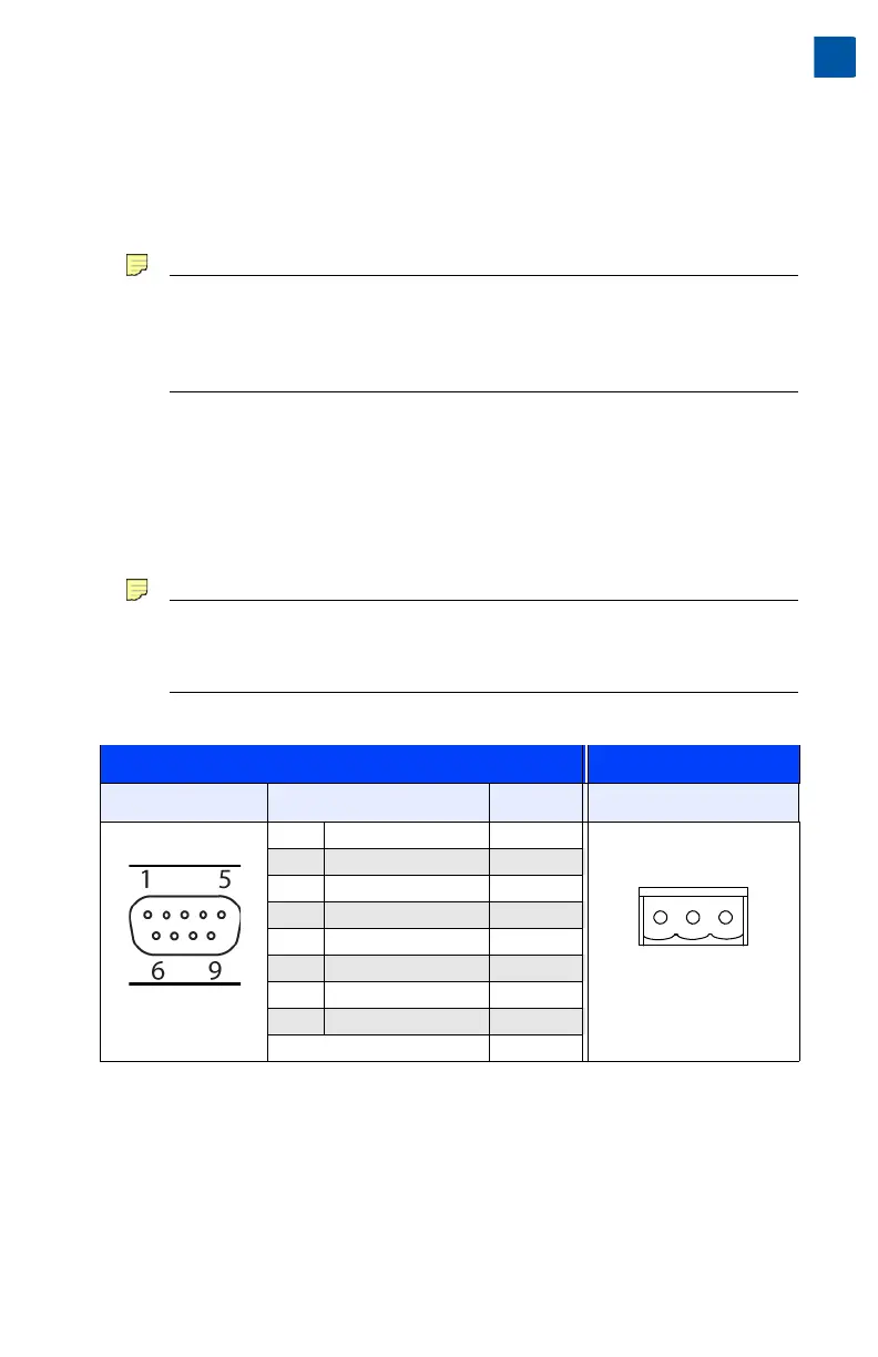
Table 3 Base serial port (RS-232 and RS-485) pinouts.
Base RS-232 DB-9 Port (COM1) RS-485 Port (COM2)
Pinout Reference Signal DB-9 Pin Pinouts
DB-9 Plug (male) DCD Data carrier detect 1 3-Position connector (male)
RXD Receive data 2
TXD Transmit data 3
DTR Data terminal ready 4
GND Ground 5
DSR Data set ready 6
RTS Request to send 7
CTS Clear to send 8
not used on the JACE 9