MOUNTING Part Number 12762 Rev 1.1 | April 30, 2014
Physical Mounting
| NETWORK CONTROLLER 3E & 6E MOUNTING AND WIRING GUIDE 9
• Mounting on a 35mm wide DIN rail is recommended. The controller’s unit base
has a molded DIN rail slot and locking clip, as do the power supply modules and
both types of I/O expansion modules. Mounting on a DIN rail ensures accurate
alignment of connectors between all modules.
• If DIN rail mounting is impractical, you can use screws in mounting tabs on the
controller, as well as any end-connected accessory (NPB-PWR, etc.). Tab mount-
ing dimensions are on the last page of this document.
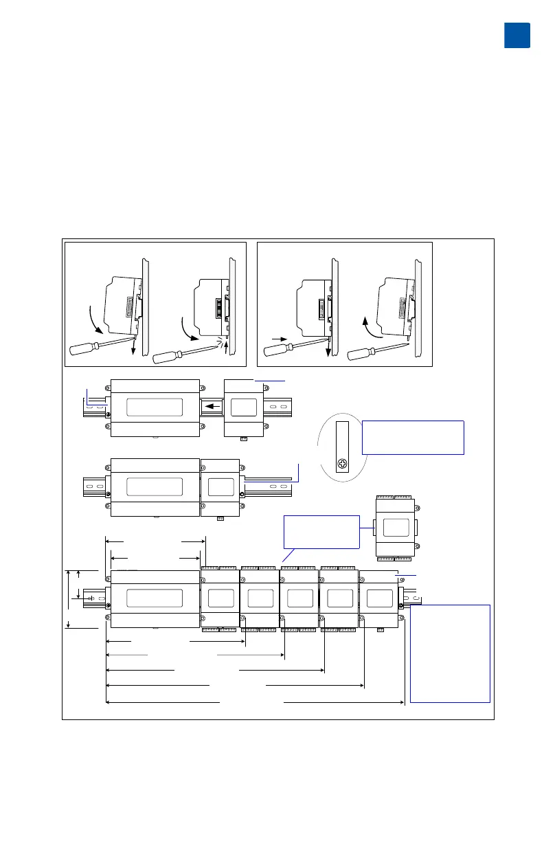
Figure 1 and the following procedure provides step-by-step DIN rail mounting
instructions for the controller.
Figure 1 T-300E or T-600E controller and accessory mounting details.
Procedure 1 To mount on DIN rail
Step 1 Securely install the DIN rail with at least two screws, near the two rail ends.
Mounting on DIN Rail
Removing from DIN Rail
Controller
7.13” (181)
6.38” (162)
10.35” (263)
13.58” (345)
16.81” (427)
20.04” (509)
23.27” (591)
4.1” (104 )
2.05” (52)
Install DIN rail End Clip
(Stop Clip) at both ends
of final assembly.
NPB-PWR or
NPB-PWR-UN
Up to four (4)
T-IO-16 modules
are supported.
DIN rail
End Clip
DIN rail
End Clip
Controller
Controller
T-IO-16
NPB-PWR or
NPB-PWR-UN
NOTE: If installing
IO modules and
using the
NPB-PWR or
NPB-PWR-UN
power supply
module, the power
supply module
installs at the end
of the chain.
T-IO-16