WIRING DETAILS Part Number 12762 Rev 1.1 | April 30, 2014
Power Wiring
| NETWORK CONTROLLER 3E & 6E MOUNTING AND WIRING GUIDE 17
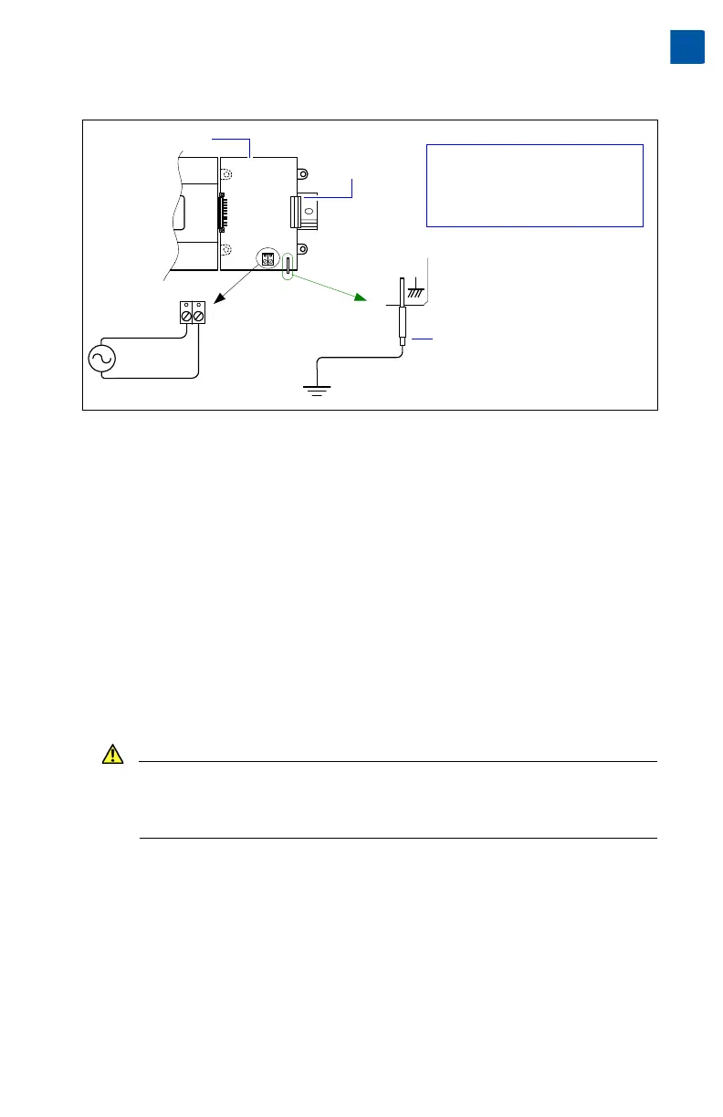
Figure 5 NPB-PWR-UN module wiring connections.
Procedure 3 Wiring NPB-PWR-UN input power and earth ground.
Step 1 Remove power from the AC circuit being wired to the NPB-PWR-UN.
See the previous Warning.
Step 2 Remove the NPB-PWR-UN cover.
To do this, press in the four tabs on both ends of the unit, and lift the cover
off. If the controller or a T-IO-16 accessory module is plugged into the unit,
you may need to slide it away to get to the cover tabs.
Step 3 Connect the supplied earth grounding wire to a nearby grounding point.
See Figure 5.
Step 4 Make AC circuit connections line (mains) and neutral to the terminals
labeled “INPUT PWR.”
Step 5 Replace the cover on the NPB-PWR-UN module.
Make sure all modules in the mounted assembly are firmly connected
together and secured.
Caution Do not energize the AC circuit wired to the NPB-PWR-UN until all other
controller mounting and wiring is completed. See “Power Up and Initial
Checkout,” page 23.
WPM-XXX (Wall Mount AC Adapter)
All models of wall power modules (US, EUR, UK) are self-contained, isolated, Class 2,
switching power supplies designed to plug into a standard building power receptacle
of appropriate voltage. To supply power to the controller, you simply plug the barrel
connector plug from the WPM-XXX into the barrel power connector on the
controller’s base board (see
Figure 3
on page 11).
Note the adapter’s 15W output rating is derated 50% at the 60°C (140°F) maximum
ambient temperature (for a controller without a NiMH battery), such that no I/O
modules are supported at 60°C. See “Environmental Requirements” on page 8.
Supplied earth
grounding wire
Earth
Ground
NOTE: The 6-pin connector on the
NPB-PWR-UN is not used with a T-300E
or T-600E series controller.
The 6-pin connector is designed for use
with other controllers or modules, and
must be left unused.
Remove cover
6-pin
connector
not used
120 or 240Vac
50–60 Hz
Single Phase
Line
Neutral
LN