General pipe connections
Pipe installation must be carried out in accordance with
current norms and directives.
The system requires the radiator circuit to be designed
for a low temperature heating medium. At the lowest
dimensioned outdoor temperature (DOT) the highest
recommended temperatures are 55 °C on the supply
line and 45 °C on the return line.
Overflow water from the evaporator collection tray and
safety valves passes via a non-pressurised pipe to an
overflow cup, and from there to a drain, so that hot wa-
ter splashes cannot cause injury. The entire length of the
overflow water pipe must be inclined to prevent water
pockets and must also be frost-proof.
NOTE
The pipe system needs to be flushed out before
the heat pump is connected so that any debris
cannot damage component parts.
Caution
Ensure that incoming water is clean. When using
a private well, it may be necessary to supple-
ment with an extra water filter.
Maximum boiler and radiator volumes
The volume of the pressure expan-
sion vessel (CM1) is 10 litres and it
is pre-pressurised as standard to 0.5
bar (5 mvp). As a result, the maxim-
um permitted height "H" between
the vessel and the highest radiator
is 5 m, see figure.
If the standard initial pressure in the
pressure vessel is not high enough
it can be increased by adding air via
the valve in the expansion vessel.
The initial pressure of the expansion
vessel must be stated in the inspec-
tion document. Any change in the
initial pressure affects the ability of the expansion vessel
to handle the expansion of the water.
The maximum system volume excluding the boiler is 219
litres at the above pre-pressure.
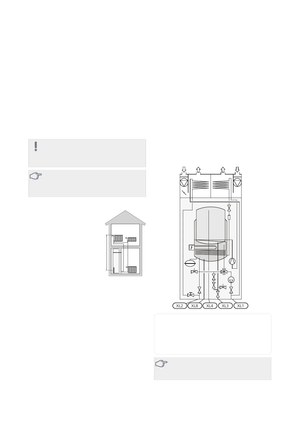
System diagram
F470 consists of a heat pump, water heater, immersion
heater, fans, circulation pump and control system.F470
is connected to the ventilation system and heating me-
dium circuit.
When the exhaust air at room temperature passes
through the evaporator, the refrigerant evaporates be-
cause of its low boiling point. In this way the energy in
the room air is transferred to the refrigerant.
The refrigerant is then compressed in a compressor,
causing the temperature to rise considerably.
The warm refrigerant is led to the condenser. Here the
refrigerant gives off its energy to the heating system
water, whereupon the refrigerant changes state from
gas to liquid.
The refrigerant then goes via filters to the expansion
valve, where the pressure and temperature are reduced.
The refrigerant has now completed its circulation and
returns to the evaporator.
Connection, heating medium flowXL1
Connection, heating medium returnXL2
Connection, cold waterXL3
Connection, hot waterXL4
Connection, dockingXL8
Caution
This is an outline diagram, differences may occur
in the actual installation.
NIBE F470Chapter 4 | Pipe and ventilation connections16
4 Pipe and ventilation connections

 Loading...


