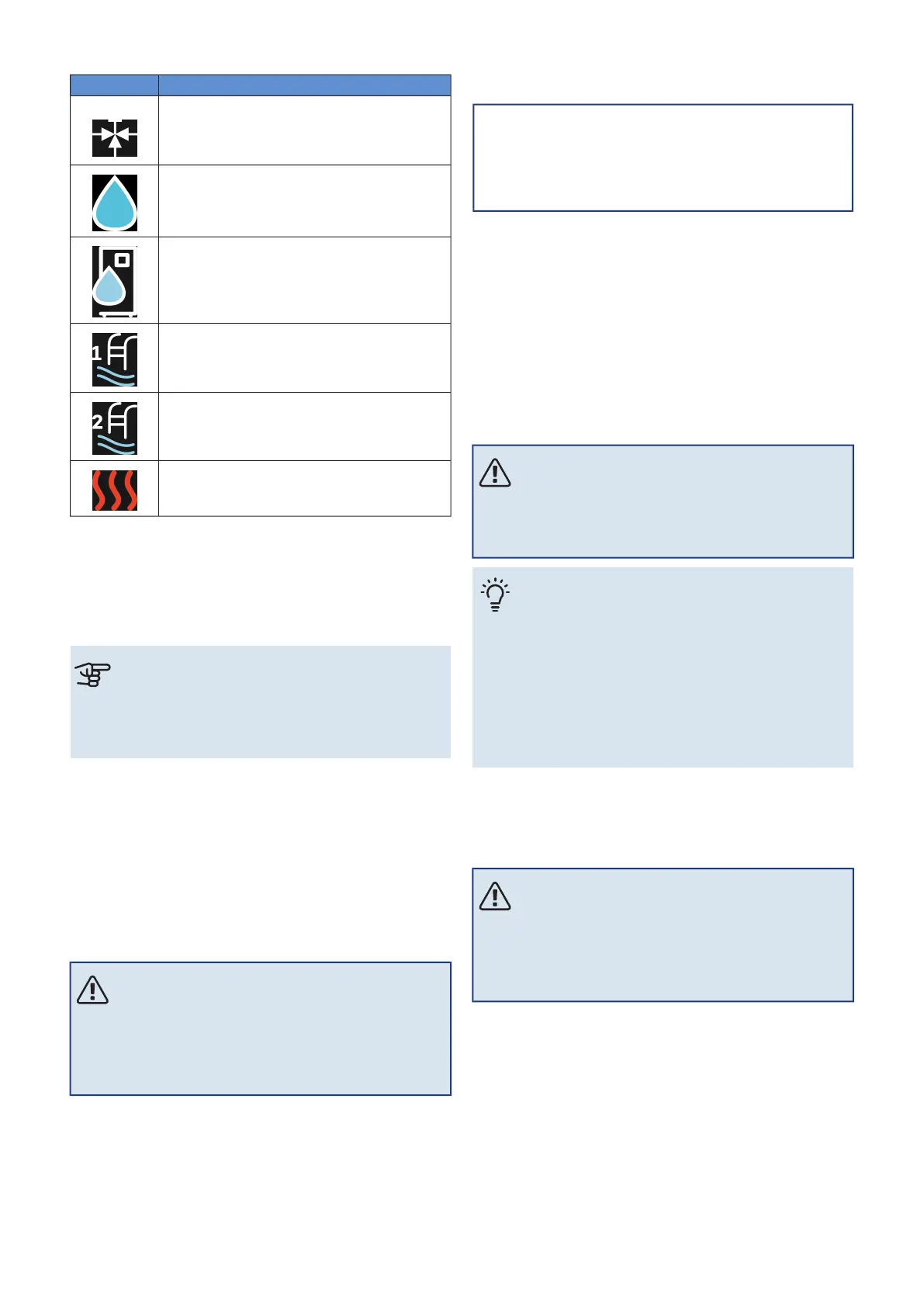
DescriptionSymbol
Shuttle valve
The designations above the reversing valve indic-
ate where it is electrically connected (EB100 = Main
unit, EB101 = Heat pump 1, etc.).
Hot water charging.
For a multi-installation: hot water with the main
unit and/or shared hot water from several different
heat pumps.
Hot water charging with subordinate heat pump
in multi-installation.
Pool 1
Pool 2
Heating (heating the building, includes any extra
climate system)
MENU 7.3.5 - SERIAL NUMBER
Here, you allocate a serial number for the system’s air/water
heat pumps. This menu is only shown if at least one connec-
ted air/water heat pump does not have a serial number, e.g.
after a circuit board has been replaced.
Caution
This menu is only shown if at least one connected
heat pump does not have a serial number. (This
can occur during service visits.)
MENU 7.4 - SELECTABLE IN/OUTPUTS
Here, you state where the external switch function has been
connected, either to one of the AUX inputs on terminal block
X28 or to the AUX output on terminal block X27.
MENU 7.5 - TOOLS
Here, you can find functions for maintenance and service
work.
MENU 7.5.1 - HEAT PUMP, TEST
NOTE
This menu and its sub-menus are intended for
testing the heat pump.
Use of this menu for other reasons may result in
your installation not functioning as intended.
MENU 7.5.2 - UNDERFLOOR DRYING FUNCTION
Length period 1 – 7
Setting range: 0 – 30 days
Temperature period 1 – 7
Setting range: 15 – 70 °C
Set the function for under floor drying here.
You can set up to seven time periods with different calcu-
lated supply temperatures. If fewer than seven periods are
to be used, set the remaining periods to 0 days.
When the underfloor drying function has been activated, a
counter is displayed showing the number of full days the
function has been active. The function counts degree
minutes in the same way as during normal heating operation,
but for the supply temperatures that are set for the respect-
ive period.
NOTE
During active underfloor drying, the heating medi-
um pump runs at 100 %, regardless of the setting
in menu 7.1.2.2.
TIP
If the operating mode "Additional heat only" is to
be used, select it in menu 4.1.
For a more even supply temperature, the additional
heat can be started earlier by setting "relative DM
start additional heat" in menu 7.1.10.3 to -80. When
set underfloor drying periods have finished, reset
the menus 4.1 and 7.1.10.3 as per previous settings.
MENU 7.5.3 - FORCED CONTROL
Here you can force control the various components in the
installation. The most important safety functions remain
active however.
NOTE
Forced control is only intended to be used for
troubleshooting purposes. Using the function in
any other way may cause damage to the compon-
ents in your installation.
MENU 7.5.6 - INVERTER REPLACEMENT
This menu includes a guide that is used during inverter re-
placement.
The menu is only visible when communication with the in-
verter is lost.
MENU 7.5.8 - SCREEN LOCK
Here, you can choose to activate the screen lock for S1256.
During activation, you will be asked to enter the required
code (four digits). The code is used when:
59Chapter 9 | Control - MenusNIBE S1256