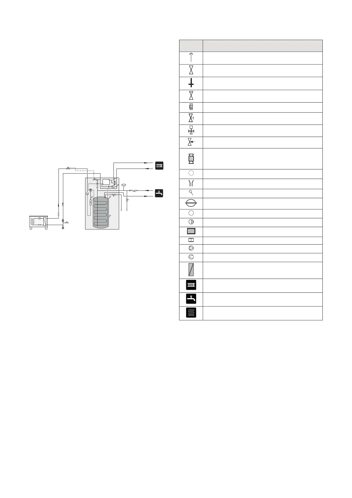
SYSTEM DIAGRAM
VVM 320 consists of water heater with charge coil, ex-
pansion vessel, safety valve, filler valve, immersion
heater, circulation pumps, buffer vessel and control
system. VVM 320 is connected to the climate system.
VVM 320 is directly adapted for connection and commu-
nication with a compatible NIBE air/water heat pump,
see page 18, and together they constitute a complete
heating installation.
When it is cold outdoors, the air/water heat pump works
with VVM 320, and if the outdoor air temperature falls
below the heat pump’s stop temperature, all heating is
carried out by VVM 320.
Requisite safety equipment connected to F2040-
8/F2040-12/F2120-8/F2120-12/HBS 05 and VVM 320,
see section, docking.
-EB101
-XL2
-XL1
-QM1
-QZ2
-QM40
-FL10
-EB15
-FL5
-EB15
-FL7
-WM3
-FL1
-RM1
-WM4
-QN17
-CM4
SYMBOL KEY
MeaningSymbol
Venting valve
Shut-off valve
Tapping valve
Non-return valve
Filterball
Trim valve
Shunt / shuttle valve
Safety valve
Filterball
Thermometer
Tundish
Temperature sensor
Expansion vessel
Pressure gauge
Circulation pump
Particle filter
Particle filter
Fan
Compressor
Heat exchanger
Radiator system
Domestic hot water
Under floor heating systems
NIBE VVM 320Chapter 4 | Pipe connections16

 Loading...


