Settings
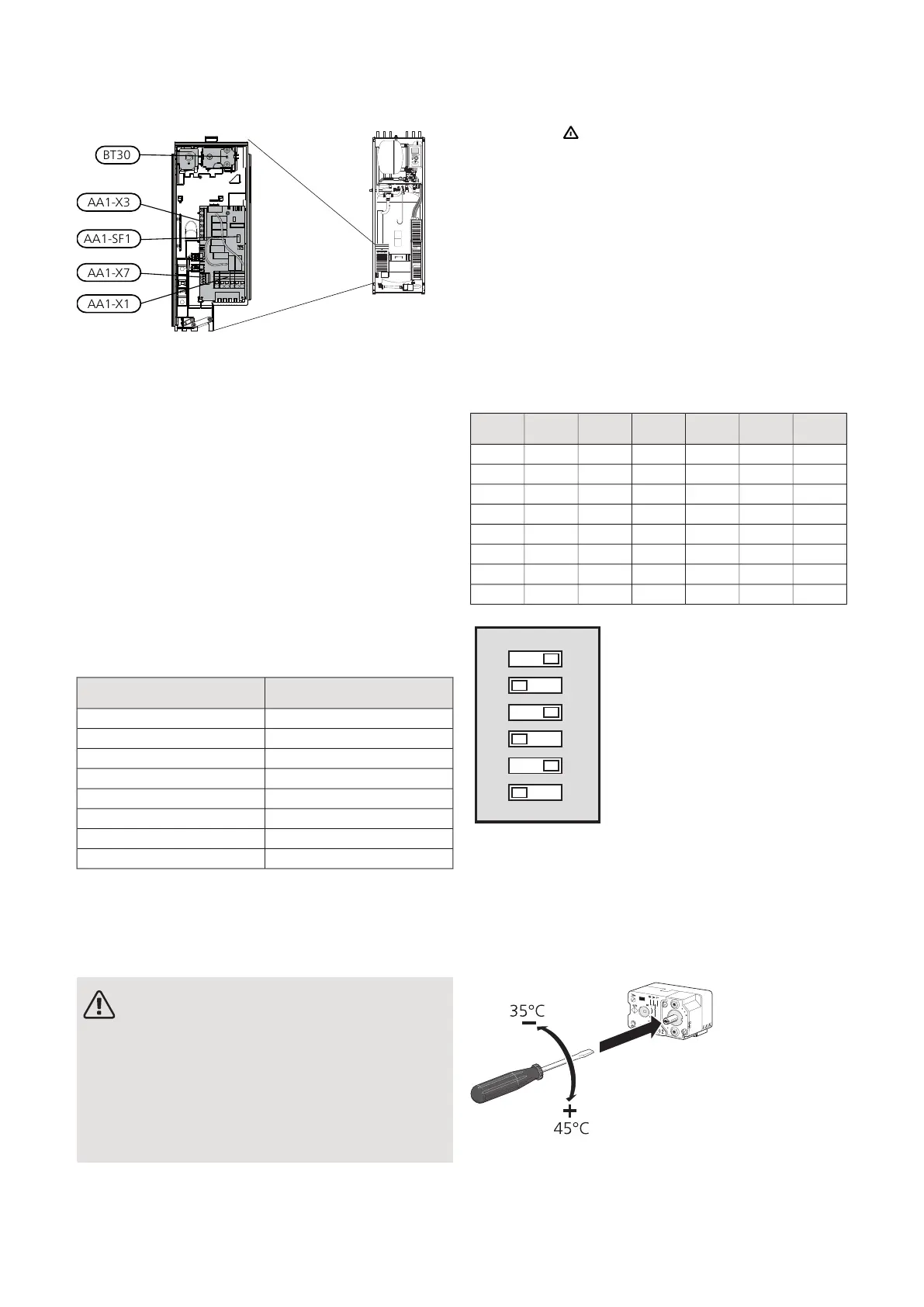
BT30
AA1-X3
AA1-SF1
AA1-X7
AA1-X1
ELECTRICAL ADDITION - MAXIMUM OUTPUT
The immersion heater can be set to a maximum of 7
kW. The delivery setting is 7 kW.
The immersion heater output is divided into 7 steps,
according to the table.
You reconnect to 7 kW by transferring the white cable
from terminal block X3:13 to terminal block X7:23 on
the immersion heater board (AA1). (The seal on the ter-
minal block must be broken.)
Setting maximum output in the electric additional heat
is done in menu 5.1.12.
Power steps of the immersion heater
1x230V (maximum electrical output, connected
upon delivery 7 kW)
Max L1 (A)Electrical addition (kW)
0.00
4.31
8.72
133
17.44
21.75
26.16
30.47
The table displays the maximum phase current for the
relevant electrical step for the indoor module.
If the current sensors are connected, the indoor module
monitors the phase currents.
NOTE
If the current sensors are not connected, the
indoor module performs a calculation of how
high the currents will be if the relevant power
steps are added. If the currents are higher than
the set fuse size, the power step is not allowed
to cut in. See chapter Load monitor on page
34.
EMERGENCY MODE
When the indoor module is set to emergency mode
(SF1 is set to ) only the most necessary functions are
activated.
• The hot water capacity is reduced.
• Fixed temperature in the flow line, see chapter
Emergency mode thermostat on page 32.
Power in emergency mode
The immersion heater’s output in emergency mode is
set with the DIP switch (SF1) on the immersion heater
board (AA1), according to the table below. The factory
setting is 6 kW.
Power in emergency mode, 1x230V (maximum
electrical output, connected upon delivery 7 kW)
654321kW
offoffoffoffoffoff0
onoffoffoffoffoff1
offoffoffonoffoff2
onoffoffonoffoff3
offoffoffonoffon4
onoffoffonoffon5
offonoffonoffon6
ononoffonoffon7
The image shows the dip-switch (AA1-SF1) in the factory
setting, that is 6 kW.
Emergency mode thermostat
The supply temperature in emergency mode is set using
a thermostat (FQ10-BT30). It can be set to 35 (preset,
e.g. underfloor heating) or 45 °C (e.g. radiators).
LEK
LEK
För markvärme!
För frånluftsvärme!
NIBE VVM 320Chapter 5 | Electrical connections32

 Loading...


