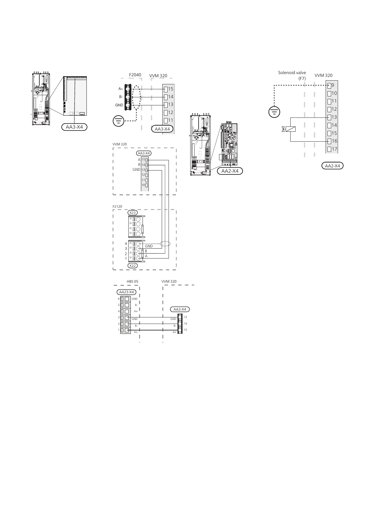
COMMUNICATION
If VVM 320 is to be connected to the heat pump, it is
connected to terminal blocks X4:13, X4:14 and X4:15
on the input board (AA3).
15
14
13
12
11
10
VV
M500F20XX
GND
B-
A+
GND
B
A
GND
B
A
X23
AA3-X4
X22
Inomhusmodul
F2120
2
1
3
4
15
14
13
12
11
10
VVM320
X22
AA3-X4
X23
X22
F2120
Innemodul
AA23
F2040
GNDGND
B-B-
A+
15
14
13
A+
GND
B-
A+
AA3
1
2
3
4
5
6
HBS 05 VVM320
AA23-X4
AA3-X4
SHUT OFF VALVE
Connect the solenoid valve (FL7) to terminal block X4:9
(PE), X4:13 (N) and X4:16 (230V) on the input board (AA2)
in VVM 320.
Solenoid valve
(F7)
VVM320
AA2-X4
31Chapter 5 | Electrical connectionsNIBE VVM 320

 Loading...


