OUTSIDE SENSOR
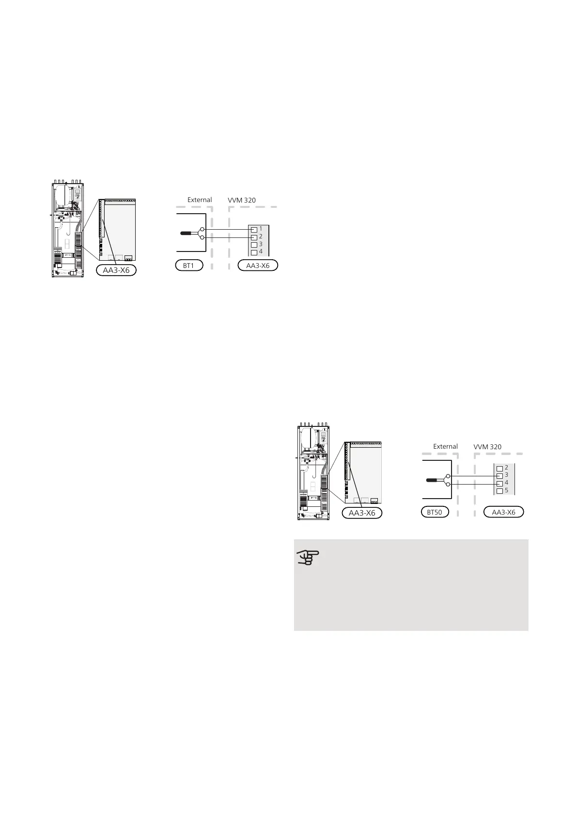
Install the outdoor temperature sensor (BT1) in the
shade on a wall facing north or north-west, so it is unaf-
fected by the morning sun for example.
Connect the sensor to terminal block X6:1 and X6:2 on
the input board (AA3). Use a twin core cable of at least
0.5 mm² cable area.
If a conduit is used it must be sealed to prevent condens-
ation in the sensor capsule.
ROOM SENSOR
VVM 320 is supplied with a room sensor enclosed
(BT50). The room sensor has a number of functions:
1.
Shows current room temperature in the display on
VVM 320.
2.
Option of changing the room temperature in °C.
3.
Provides the option of fine-tuning the room temper-
ature.
Install the sensor in a neutral position where the set
temperature is required. A suitable location is on a free
inner wall in a hall approx. 1.5 m above the floor. It is
important that the sensor is not obstructed from meas-
uring the correct room temperature by being located,
for example, in a recess, between shelves, behind a
curtain, above or close to a heat source, in a draft from
an external door or in direct sunlight. Closed radiator
thermostats can also cause problems.
The indoor module operates without the sensor, but if
one wishes to read off the accommodation's indoor
temperature in VVM 320's display, the sensor must be
installed. Connect the room sensor to X6:3 and X6:4 on
the input board (AA3).
If the sensor is to have a controlling function, it is activ-
ated in menu 1.9.4.
If the room sensor is used in a room with underfloor
heating, it should only have an indicatory function, not
control of the room temperature.
AA3-X6BT50
External
VVM320
Caution
Changes of temperature in accommodation
take time. For example, short time periods in
combination with underfloor heating will not
give a noticeable difference in room temperat-
ure.
NIBE VVM 320Chapter 5 | Electrical connections30

 Loading...


