General
All electrical equipment, except the outdoor sensors,
room sensors and the current sensors are ready connec-
ted at the factory.
• Disconnect the indoor module before insulation testing
the house wiring.
• If the building is equipped with an earth-fault breaker,
VVM 320 should be equipped with a separate one.
• For the indoor module wiring diagram, see page 74.
• Communication and sensor cables to external connec-
tions must not be laid close to high current cables.
• The minimum area of communication and sensor
cables to external connections must be 0.5 mm² up
to 50, for example EKKX or LiYY or equivalent.
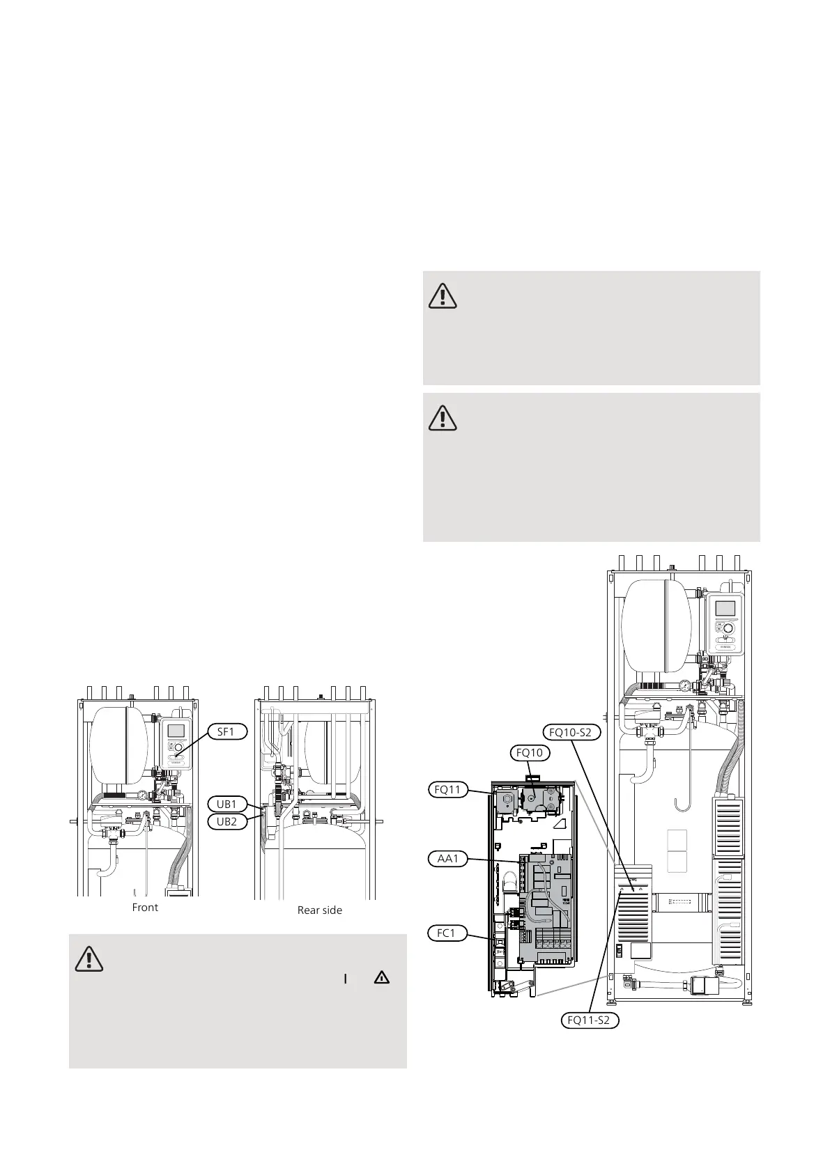
• When cable routing in VVM 320, cable grommets
UB1and UB2, (marked in image) must be used. In UB1
and UB2, the cables are inserted through the indoor
module from the back to the front.
NOTE
The switch (SF1) must not be set to "" or " "
until the boiler has been filled with water and
the radiator system vented. Otherwise the
temperature limiter, thermostat and the immer-
sion heater can be damaged.
NOTE
If the supply cable is damaged, only NIBE, its
service representative or similar authorised
person may replace it to prevent any danger
and damage.
NOTE
Electrical installation and service must be car-
ried out under the supervision of a qualified
electrician. Cut the current with the circuit
breaker before carrying out any servicing.
Electrical installation and wiring must be carried
out in accordance with the stipulations in force.
FQ10-S2
FQ11
AA1
FC1
FQ10
FQ11-S2
NIBE VVM 320Chapter 5 | Electrical connections26
5 Electrical connections

 Loading...


