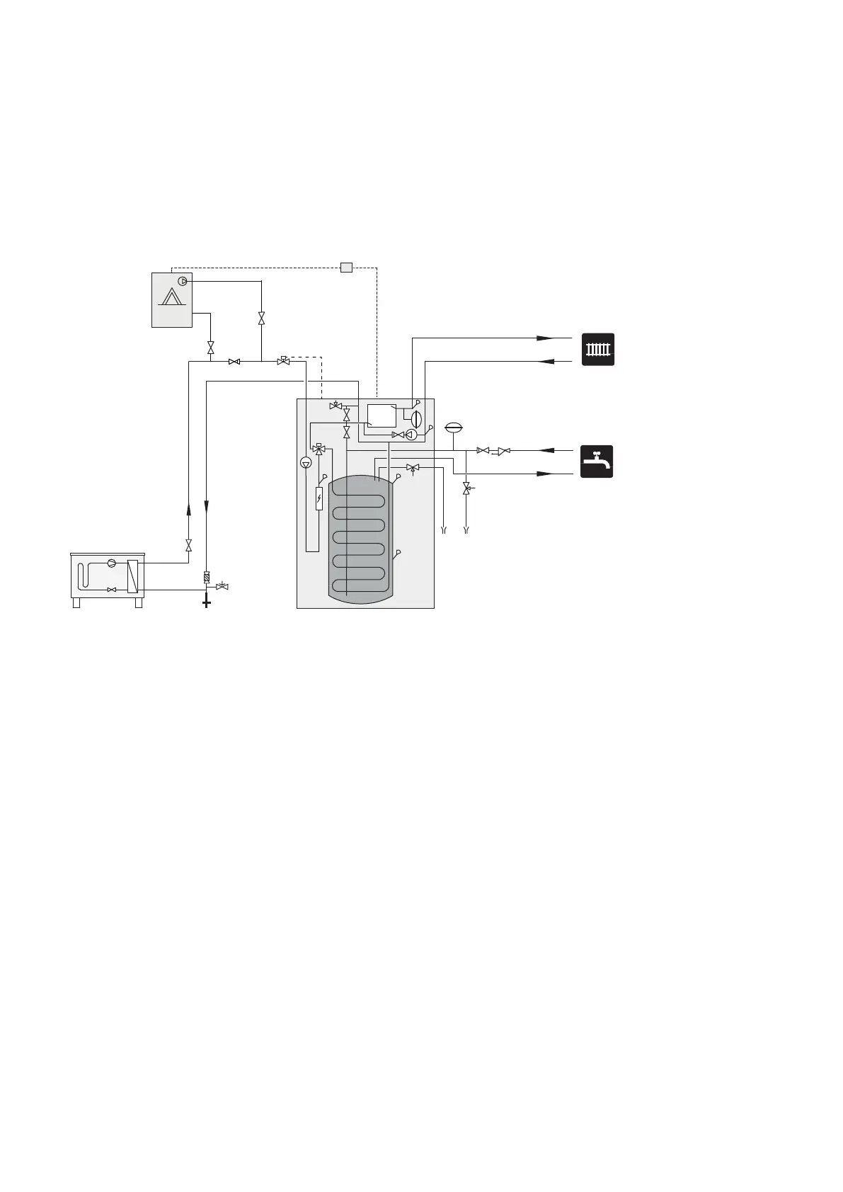
CONNECTION OF OPT 10 AND GAS BOILER GBM 10-15
GBM 10-15 is connected to the supply line, between the indoor module and the air/water heat pump. For connection
of GBM 10-15, the accessory OPT 10 is required, see "Accessories" on page 69.
The indoor module controls the gas boiler's requested supply temperature via OPT 10. The gas boiler then regulates
its own output to achieve the requested temperature.
In menu 4.1.8, you choose if you wish to use "smart energy source™". Here you can choose if the system is to
use the energy source that is cheapest at the time. It is also possible to choose if the system is to use the energy
source that is most CO
2
neutral at the time.
-EB101
-XL2
-XL1
-QM1
-FL10
-QM40
-QZ2
-EB15
-FL5
-EM1
-AA25
-EM1
-EM1
-RM1
-EM1
-QM42
-EM1
-QM43
-EB15
-FL7
-WM3
-FL1
-RM1
-WM4
-QN17
-CM4
25Chapter 4 | Pipe connectionsNIBE VVM 320

 Loading...


