23
20 - ACCESSORY INPUTS AND OUTPUTS
GATE OPERATOR ACCESSORY INPUTS:
Auxiliary Inputs 1 (16), 2 (18): These digital inputs may be connected to
the digital outputs of accessories and programmed to activate or control the
gate operator in a number of different modes. Shorting the pins through a dry
contact activates the programmed settings for these inputs. These inputs are
programmed in the “FUNCTION Auxiliary I/O” menu.
SAFETY Input: (22) Dry contact input that can be programmed for an inductive
loop or photo-eye detector. Shorting the Safety Input (22) to GND reverses a
closing gate to the full open position. The opened gate is held opened for as
long as the input is active. This input is not for external entrapment sensors.
SHADOW Input: (24) Dry contact input that can be programmed for an
inductive loop or photo-eye detector. Shorting the Shadow Input (24) to GND
maintains an OPEN gate fully open and a CLOSED gate fully closed until
deactivated.
Setting the Shadow Input to “Photo Mode” causes the opening gate to stop,
then reopens the gate when the Shadow Input is deactivated.
ENTRAP Input: (26) Dry contact input that can be programmed for an
inductive safety loop or photo-eye detector. Shorting the ENTRAP input (26)
to GND while the gate is opening cause the gate to close to the fully closed
position. This input is not for external entrapment sensors.
EDGE Input: (28) This input may be congured as “DIGITAL” NO or “ANALOG”
as required by the sensor type. When congured as “DIGITAL”, this is a dry
contact input. When congured as “Analog”, there are additional options for
the direction of travel it is intended to protect: Open, Close, or Both (swing
only). When congured as “Analog” the input must measure an 8.2K - 10K
ohm resistor. When the input is activated and set to Digital, the gate stops and
reverses regardless of direction. If set to “Analog” the gate will only reverse if
tripped while going in the programmed direction..
EXIT Input: (30) Dry contact input for a vehicle exit sensor. Shorting the EXIT
input to GND opens gate from the closed position and holds gate open with
maintained input or reverses gate if closing.
FIRE Input: (32) Dry contact input for a re department control switch. Shorting
the Fire input (32) to GND opens the gate and holds the gate open until the
control switch is deactivated. This input is “hold to run”. Auto-close is disabled
when this input is activated. Also clears hard shutdown.
GUARD STATION
Guard Station OPEN: (34) Dry contact input for a guard station open switch.
Momentarily shorting the Open input (34) to GND opens the gate to the full
open position with the subsequent auto-close feature enabled.
Guard Station STOP: (35) Dry contact input (Normally Closed) for a guard
station stop switch. Momentarily opening the Stop input (35) stops the opening
gate at its current position. While this input is activated, all other inputs are
disabled and are not functional.
Guard Station CLOSE: (36) Dry contact input for a guard station close switch.
Momentarily shorting the Close input (36) to GND closes the gate (master and
slave).
RADIO
Radio Open: (39) Dry contact input for an accessory radio open switch.
Momentarily shorting the Open input (39) to GND opens the gate to the full
open position with the subsequent auto-close feature enabled.
Radio Close: (40) Dry contact input for an accessory radio close switch.
Momentarily shorting the Close input (40) to GND closes the gate.
Radio Input: Open/Close: (39 and 40) If you tie open and close together the
unit will operate as a Step by Step command each time the input is shorted to
GND, it will either OPEN, STOP or CLOSE.
20.1 - Outputs
Figure - BOARD OUTPUTS
GATE OPERATOR ACCESSORY OUTPUTS:
OUT1 and OUT2: Individual, isolated relays provide COMMON, NORMALLY
OPEN, and NORMALLY CLOSED dry contacts for switching accessories
based on programming of the “Auxiliary IO” function. These outputs are
programmed in the “FUNCTION Auxiliary I/O” menu.
Magnetic Lock: Provides fused power (1.85A max) and isolated relay
COMMON, NORMALLY OPEN, and NORMALLY CLOSED dry contacts for
electrically powered and maintained magnetic locks. The output time for
magnetic lock activation/deactivation may be adjusted from 0 to 5 seconds.
Lamp: Provides fused power (1.85A max) to drive a ashing warning lamp
to indicate gate operation. This output is active when the gate is operating
(Opening and Closing). Lamp Delay sets the amount of time the lamp
accessory output is activated prior to gate movement. Settings from 0 to 5
seconds with a step of 0.5 seconds.
Alarm: Provides fused power (0.5A @ 12VDC) to drive an alarm siren
to signal the occurrence of a hard shutdown, caused by 2 consecutive
entrapment events (signals). This alarm output is reset by pressing the “Reset
Hard Shutdown” button on the front panel or activating the “FIRE” input.
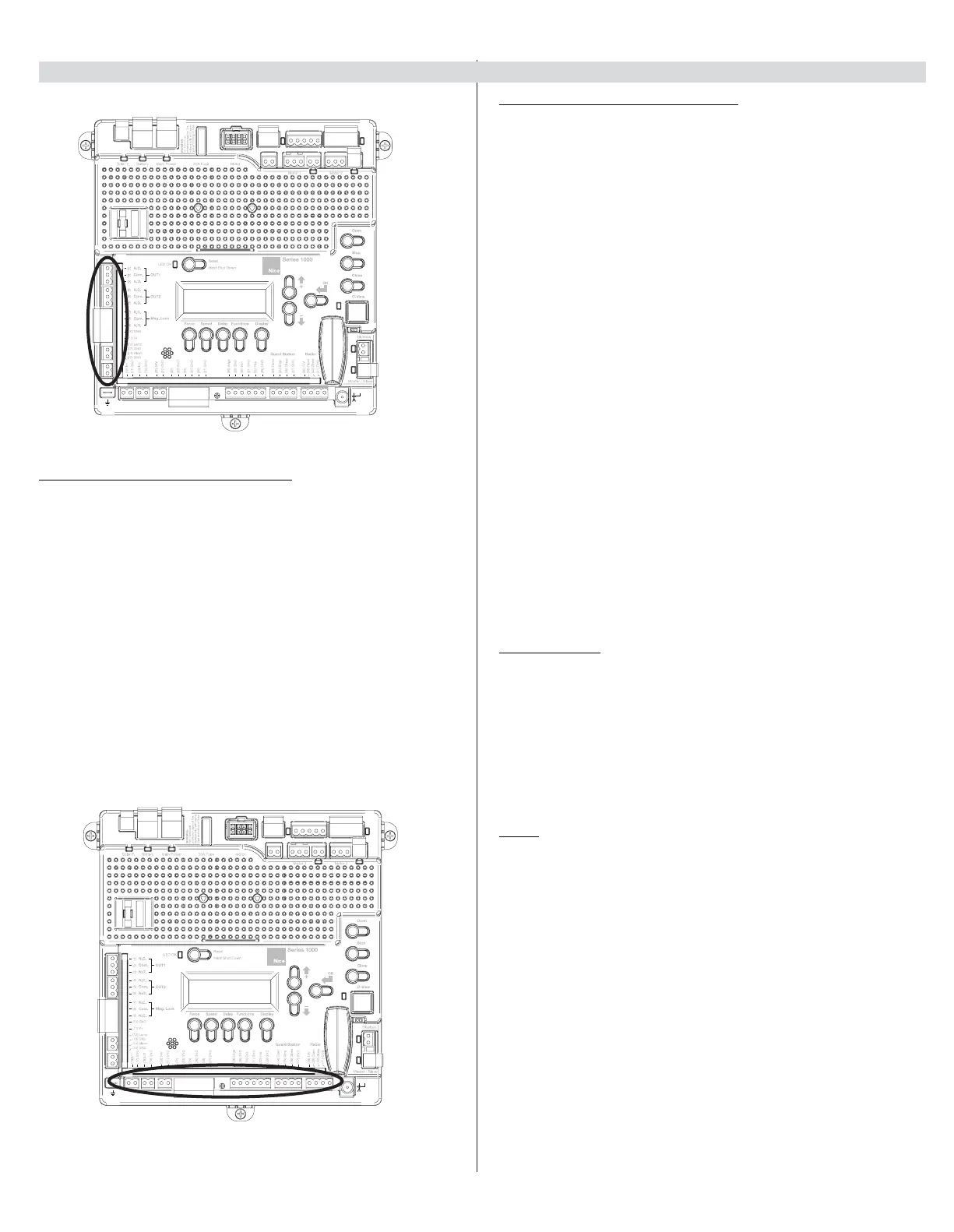
20.2 - Inputs
Figure - INPUTS
Safety
Shadow
Entrap
Shadow
Safety
Shadow
Entrap
Shadow