25
21 - 120VAC POWER WIRING
Table 1 - MAXIMUM RUN (FT) PER WIRE GAUGE
110V AWG
14
180
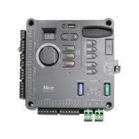
Deleting all Nice transmitters from the Nice Plug-In Receiver Memory.
All programmed remote controls may be removed from the Nice plug
in receiver memory . This procedures need to be performed at the gate
controller.
1. Press and hold the button on the side of the Nice receiver until the led on
the Nice receiver illuminates green and keep the button pressed.
2. Watch the led and on the receiver and verify the following sequence in the
led.
3. Within 4 seconds after pressing the button (approx.) the green led
illuminates.
4. Within 8 seconds after pressing the button (approx.) the green led turns
off.
5. Within 12 seconds after pressing the button (approx.) the green led starts
ashing
6. Count the green led ashes on the Nice receiver. On EXACTLY the 3
rd
ash,
release the button on the Nice receiver.
7. It is recommended to test the Nice remote controls, if available, with Nice
plug in receiver to verify that it no longer affects the gate controller.
DO NOT WIRE AC POWER TO THE 1050 CONTROL BOARD!
THE CONTROL BOARD OPERATES ON 10 - 32 VDC ONLY!
This section is intended for residential systems where a 120VAC
transformer will be used
To reduce the risk of SEVERE INJURY or DEATH:
• Disconnect power to the gate operator by manually opening its dedicated
circuit breaker before making any mechanical or electrical adjustments.
• Use a 20 Amp dedicated circuit breaker for each installed gate operator.
• Open dedicated circuit breaker supplying power to gate operator BEFORE
a new installation or making any modications to an existing installation of
this gate operator.
• All wiring connections MUST be made by a qualied individual
• Run individual circuits in separate U.L. listed conduits. Do not combine
high voltage (120VAC) power wiring and low voltage (+12VDC to +24VDC)
control wiring in the same conduits.
• Use the information in Table 1 to determine high voltage wire size
requirements. The distance shown in the chart is measured in feet from the
operator to the power source. If power wiring is greater than the maximum
distance shown, it is recommended that a service feeder be installed.
When large gauge wire is used, a separate junction box must be installed
for the operator connection. The wire table is based on stranded copper
wire. Wire run calculations are based on a 110 VAC power source with a
3% voltage drop on the power line, plus an additional 10% reduction in
distance to allow for other losses in the system.
The gate operator system should be grounded through the earth ground
in the AC mains wiring system (GREEN WIRE). This ground connection will
prevent dangerous currents from appearing on the metal control box, the
actuator, or the gate itself.
DO NOT WIRE AC MAINS POWER TO THE METAL CONTROL BOX
WITHOUT AN EARTH GROUND CONNECTION!
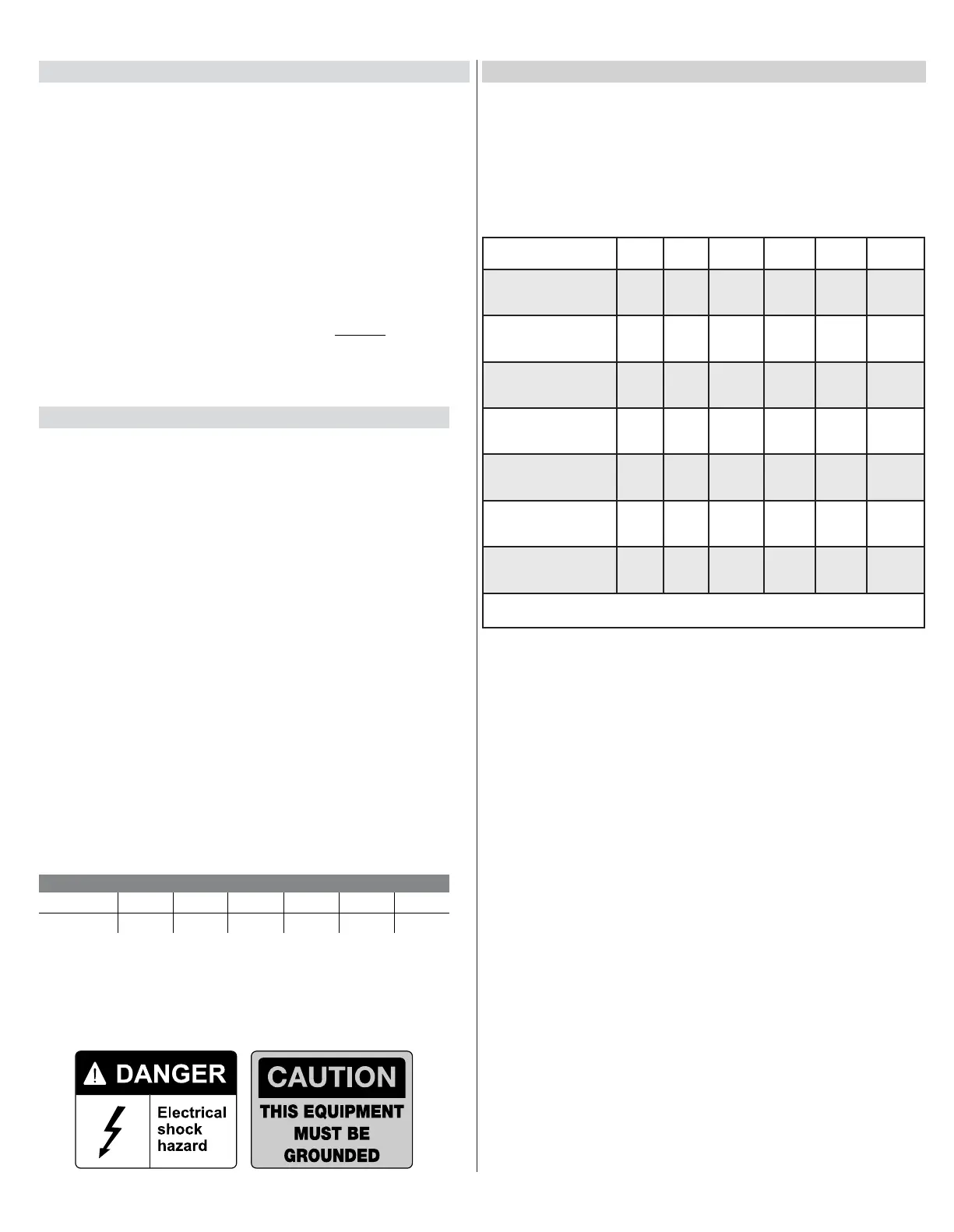
22 - SOLAR PANEL CHART
Daily cycles 1-10 1-20 1-40 1-60 1-80 80+
5 watt solar panel
*
10 watt solar panel
*
20 watt solar panel
(requires regulator)
*
30 watt solar panel
(requires regulator)
*
40 watt solar panel
(requires regulator)
*
1.5 amp battery
charger
*
10 amp battery
charger
*
Note: Double the amount of solar wattage for dual gate operators
This Nice Operator is 12 Volt DC (Direct Current) powered. A 12 Volt sealed battery
(33 ampere hour minimum for AC charged systems, 70 ampere hour minimum for
solar charged systems) with connecting posts located on the top is recommended.
The following table should be used as a guide for capacity of operation of
operators only, additional options and accessories may reduce the daily usage.
Please note that the charge capability of solar panels will vary with different
geographical locations.
Nice operators with the 1050 board that are used in solar applications need to be
put into “Standby” mode.
To do this, press:
Function scroll to #8 "Standby" OK Select desired amount of
time before system enters, "Standby Mode" OK
Once this is done, the operator will enter a Standby mode after the set time when
the operator is not moving or in the auto-close countdown.
Things to note in Standby:
1. Display will be off and only a “heartbeat” will be present at the LED OK
2. Voltage at terminal #20 (24 volts) and terminal #38 (12 volts) will turn off - DO
NOT POWER ENTRY OR EXIT DEVICES HERE
3. BlueBus function disabled until board "wakes"
4. Master/Slave syncing is non functional (used for commercial operators only)
Connection of the solar panel(s) may be made at the top left corner of the board
at “Solar P” (regulated charging to the “Battery” via the controller in the board) –
note that the maximum output of the regulator in the 1050 board is 1.5A. If the
installation requires larger than a 30W solar panel – an off-board regulator should
be used and connected directly to the battery.
20 - ACCESSORY INPUTS AND OUTPUTS (CONT.)
MAX RUN (ft)
12 10 8 6 4
280 460 700 1150 1800