1 - OVERVIEW 4
2 - General Safety Information 6
3 - Use of Vehicle Detectors 9
4 - Gate Construction and Safety 9
5 - Maintenance of Gate Systems 11
6 - Entrapment Protection 12
7 - Compatible External Sensors 13
8 - PARTS IDENTIFICATION 14
9 - PULL TO OPEN INSTALLATION 15
10 - PUSH TO OPEN INSTALLATION 16
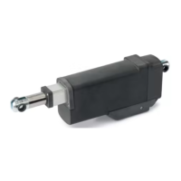
11 - ACTUATOR MOUNTING 16
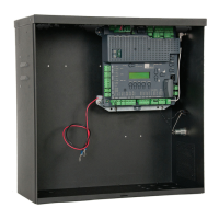
12 - CONTROL BOX MOUNTING 17
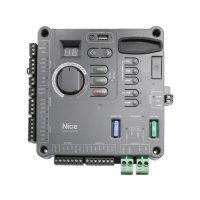
13 - 1050 CIRCUIT BOARD LAYOUT 17
14 - INCOMING POWER WIRING 18
15 - ACTUATOR WIRING 19
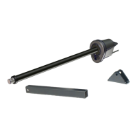
16 - GATE BRACKET MOUNTING 20
17 - LIMIT SWITCH ADJUSTMENT 20
18 - SETTING LIMIT SWITCHES 21
19 - LEARNING MODE 22
20 - ACCESSORY INPUTS AND OUTPUTS 23
20.1 - Outputs 23
20.2 - Inputs 23
20.3 - Communication buses 24
20.4 - Programming the plug-in receiver and remote controls 24
21 - 120VAC POWER WIRING 25
22 - SOLAR PANEL CHART 25
23 - EXAMPLE WIRING CONNECTIONS 26
23.1 - Fire dept. connection 26
23.2 - Magnetic lock connection 26
23.3 - Guard station 26
23.4 - Exit and edge inputs wiring diagram 26
23.5 - Radio receiver connection (third party) 27
23.6 - Optional power output 27
24 - INSPECTION AND OPERATION 27
25 - GENERAL LAYOUT AND SAFETY ACCESS 28
26 - ACCESSORIES AND SENSORS 29
27 - IRB-BET WIRING DIAGRAM 30
28 - GEM-103 WIRING DIAGRAM 30
29 - WEL-200 WIRING DIAGRAM 31
30 - BOARD NOMENCLATURE 32
31 - PROGRAMMING BUTTONS 33
31.1 - Force 33
31.2 - Speed 33
31.3 - Acceleration 33
31.4 - Delay 33
31.5 - Function 33
31.6 - Display 34
32 - EMERGENCY VEHICLE ACCESS 35
33 - GLOSSARY 35
34 - MAINTENANCE SCHEDULE 36
35 - TROUBLESHOOTING 36-37
36 - OPERATOR DIMENSIONS 38
36.1 - Control box dimensions 38
36.2 - Actuator dimensions 39
37 - EXPLODED VIEW 40
37.1 - Control box 40
37.2 - Actuator - Front 41
37.3 - Actuator - Back 42
38 - WARRANTY 43
39 - INSTALLATION CHECKLIST 44
40 - Appendix - French Translations 45-48
TABLE OF CONTENTS