Mercury 310 Automated Gate System
Installation and Programming Manual
2525
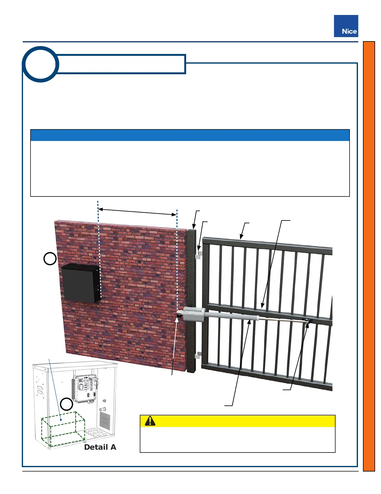
1. Mount the control box on the same side as the primary actuator (for dual gate systems, the same side
as the actuator with shorter harness) and at least six feet away from pivot arm and moving parts of the
gate (see below).
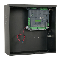
2. Set 12V backup battery inside of control box with terminals toward the front (see Detail A below).
SolarBOX310 Installation Location
Detail A
1
Install SolarBOX310
CAUTION
Do not mount the control box where the person using the control
box to operate the gate can come in contact with the gate!
NOTICE
’ The image below shows a typical install. The control box may be installed on either side of the wall
depending on which direction the gate opens or where a person monitoring the gate will be located.
’ Mounting hardware for the control box is NOT included. Drill holes as needed in mounting surface
and use hardware capable of supporting weight of control box (23 lbs [10.5 kg]) PLUS the battery,
which can add up to 66lbs (30 kg), depending on the battery selected.
Suggested
Battery
Location
Control Control
BoxBox
WallWall
Gate
Hinge Post
Gate
Hinge
Structural Gate
Support
1.
2.
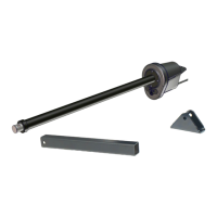
SolarBOX310
Pivot Arm Location
(in line with structural
support on gate)
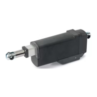
Linear Actuator
Gate Bracket
6 Foot Minimum
www.ApolloGateOpeners.com | (800) 878-7829 | Sales@ApolloGateOpeners.com