13
Connect #2 wire from the
keypad to the COM
terminal on the gate
opener control board.
Connect #1 wire from the
RELAY OUTPUT terminals
on the keypad to the
CYCLE terminal on the gate
opener control board.
#2
#1
POWER
LED3
D15
R20
IC4
D16
D13
D14
K2
BATT- BATT+
EDGE
COM
LOCK+
LOCK -
M_BLK
M_RED
VAR2
GRN
VAR3
VAR3
VAR1
VAR4
VAR5
PF1
VAR6
WHT
CYCLE
EXIT
SAFETY
COM
CHGR
CHGR
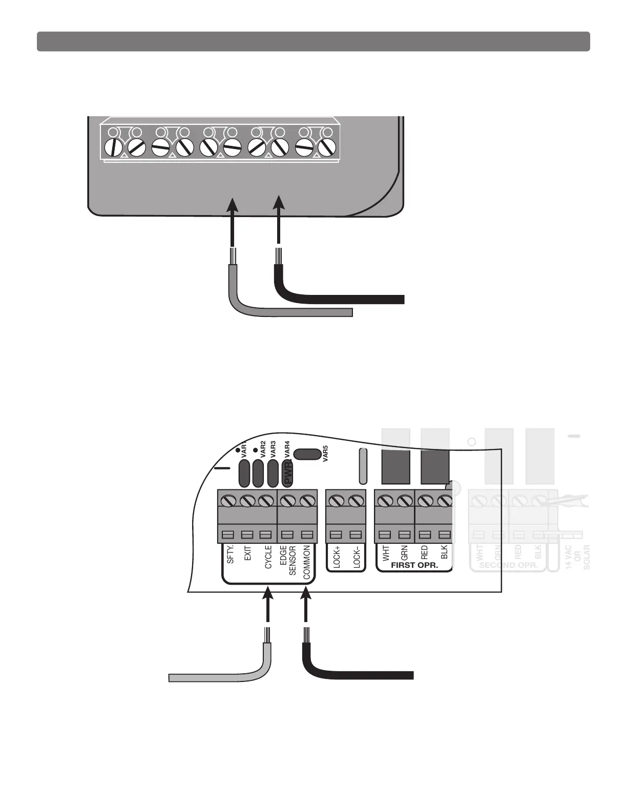
Connect #1 wire from the
RELAY OUTPUT terminals
on the keypad to CYCLE
terminal on the gate opener
control board.
Connect #2 wire from the
keypad to the COMMON
terminal on the gate opener
control board.
#1
#2
VAR5
K1
PF1
K2
BATT +
K3
K4
VAR4
VAR3
VAR2
VAR1
PWR.
SFTY.
EXIT
CYCLE
EDGE
SENSOR
COMMON
LOCK+
LOCK–
WHT
GRN
RED
BLK
WHT
GRN
SECOND OPR.FIRST OPR.
RED
BLK
14 VAC
OR
SOLAR
MM271 Control Boards
MM262, MM362, MM462, FM202, PRO-SW2000XLS Series Control Boards
Control Board Connections