5
The Keypad
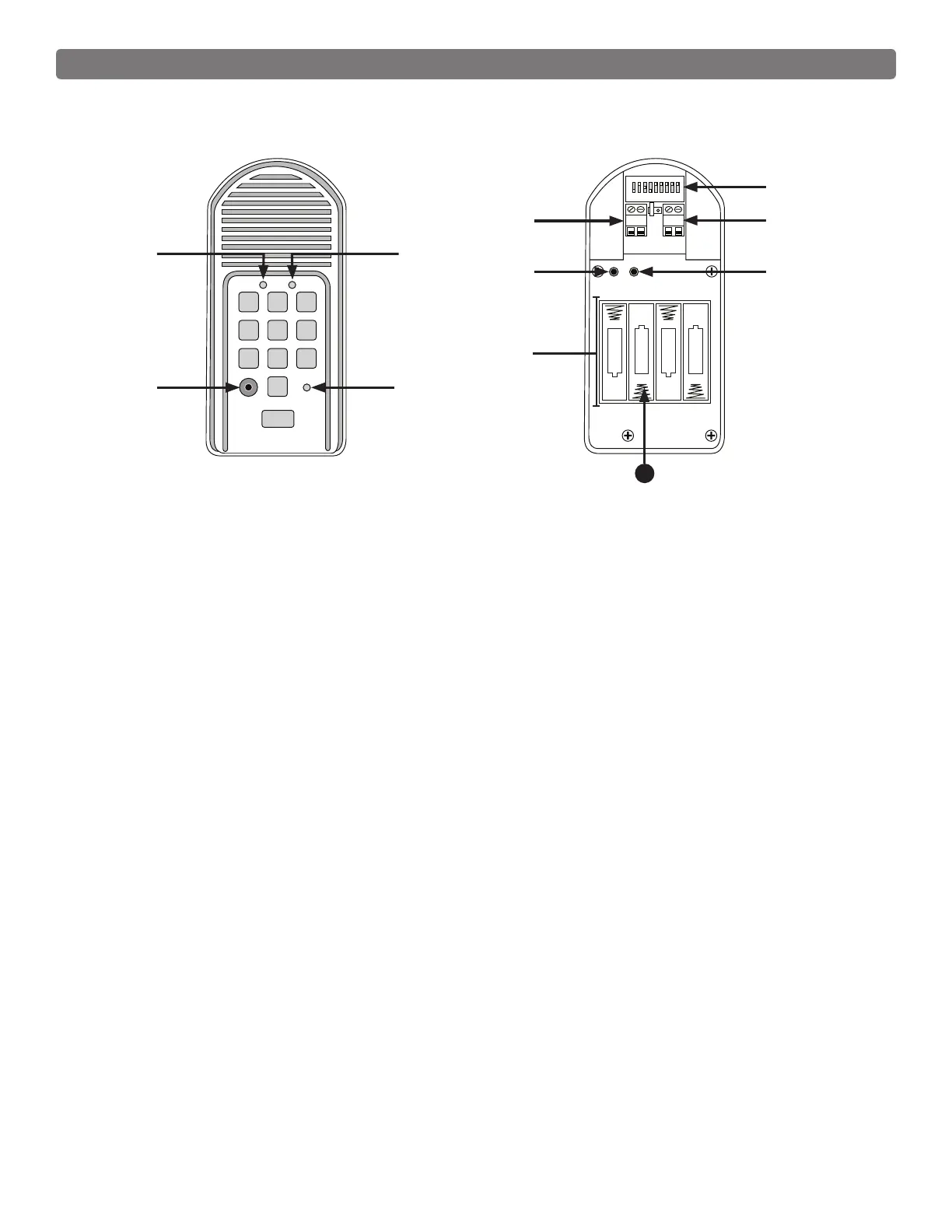
Front
1. CALLING Light: LED is RED when calling and turns GREEN when call is answered.
2. GRANTED Light: LED turns GREEN when access permission is granted.
3. Program button: Used to program access codes.
4. Status Light: This led will blink once when any key is pressed and provides visual feedback during
access code programming.
5. DIP Switches: Match these switches to your remote transmitter to program the keypad.
6. Power Input: Used to connect keypad to gate opener for continuous power supply.
7. Relay output: Used to connect Keypad to gate opener in hard-wired applications.
8. ID SET button: This button is used only when there is another pair of Mighty Mule wireless.
9. Reset button: Pressing this button for 2 seconds will reprogram key pad to factory settings. All codes
are deleted. Default master code is 1234.
10. Battery Holder: Use 4 AA batteries if hard-wired power supply is not used. If external power source is
used the 4 AA batteries will provide a back-up power source.
11. Batteries
Installing the Batteries
Four (4) AA batteries are required to power the keypad (if wireless use).
• Remove the two screws from the bottom of the keypad and separate the keypad from its housing.
• Install four (4) AA batteries as necessary (not included).
If an external DC power supply is used, the batteries (not required) will act as a back up. Low voltage wire
from the gate opener battery must be connected to the POWER IN terminals on the keypad control board.
1 2
ABC
3
DEF
4
GHI
5
JKL
6
MNO
7
PRS
8
TUV
9
WXY
0
CALL
STATUS
PROGRAM
CALLING
GRANTED
RELAY
OUTPUT
AC/DC
POWER IN
123456789
+
0
–
ID SET
+
–
–
–
+
+
–
+
RESET
JUMPER
Inside
11