EN
6 – English
The control unit has 3 keys OPEN (), STOP (SET), CLOSE (u) that can be
used both for controlling the unit during testing and for programming the avail-
able functions.
The programmable functions available are divided into 2 levels and their relative
operating status is displayed by means of the 8 LEDs (L1…L6) on the control unit
(LED lit
= function active; LED off = function not active).
Use the programming keys:
OPEN (): – key for controlling gate opening; – selection key during program-
ming.
STOP/SET: key for stopping a manoeuvre; if pressed for more than 5 seconds,
it enables entry to programming mode.
CLOSE (u): – key for controlling gate closure; – selection key during programming.
6.1 - Level one programming (ON-OFF functions)
All level 1 functions are set by default to “OFF” and may be modified at any time.
To check the functions see Table 5. For the programming procedure see Table 6.
IMPORTANT – In the programming procedure, the maximum time interval that
can elapse between activation of one key and the next is 10 seconds. When
this time elapses, the procedure terminates automatically, memorising the mod-
ifications made up until then.
PROGRAMMING THE CONTROL UNIT
6
TABLE 5 - First level functions
Led Function Description
L1 Automatic closure
L2 Reclose after photo
L3 Always close
L4 All standby
L5 lock/Courtesy light
L6 Pre-flash
L7 “Step-Step” becomes “Open”
and “Open” becomes “Close”
L8 “Flash” or “Gate Open Indicator”
ACTIVE function: after an opening movement, there is a pause (equal to the programmed time) after which
the control unit automatic initiates a closure movement. The factory setting for the Pause time is 30 sec.
Function NOT ACTIVE
: function is “semiautomatic” type”.
ACTIVE function
: if the photocells are activated during the opening or closing manoeuvre, the pause time
is reduced to 5 seconds regardless of the programmed pause time.
With “automatic closure” disabled, if the photocells are activated during closure the “automatic closure” is
activated with the programmed “pause time”.
ACTIVE function
: in the event of a power failure, even of short duration, when power is restored the con-
trol unit detects gate open and automatically starts a closure manoeuvre, preceded by 5 seconds of pre-
flashing.
Function NOT ACTIVE
: when power is restored the gate remains where it is.
ACTIVE function
: after 1 minute from the end of the manoeuvre, the control unit turns off the “BlueBus” out-
put (connected devices), Bus T4 (connected devices), the outputs flash and ELS, some internal circuits and
all leds with the exception of the BlueBus led, which flashes at a slower interval. When the control unit recei-
ves a command, it resumes normal operation (after a short delay). This function is used to reduce consum-
ption, an important aspect in the case of battery powered devices or when using photovoltaic panels.
ACTIVE function
: the “electric lock” output switches its operation to “courtesy light”.
Function NOT ACTIVE
: the output operates as an electric lock.
ACTIVE function
: adds a pause of 3 seconds between switch-on of the flasher and the beginning of the
manoeuvre, to signal a dangerous situation in advance.
Function NOT ACTIVE
: the signalling of the flasher coincides with the beginning of the manoeuvre.
ACTIVE function
: the two inputs “Step-step” and “Open” of the control unit have the functions “Open" and
“Close”.
Function NOT ACTIVE
: the two inputs “Step-step” and “Open” of the control unit have the functions “Step-
step" and “Partial Open 1”.
ACTIVE function
: the “flash” output of the control unit switches operating mode to “gate open indicator”.
Function NOT ACTIVE
: the "FLASH" output of the control unit performs the “Flashing light” function”.
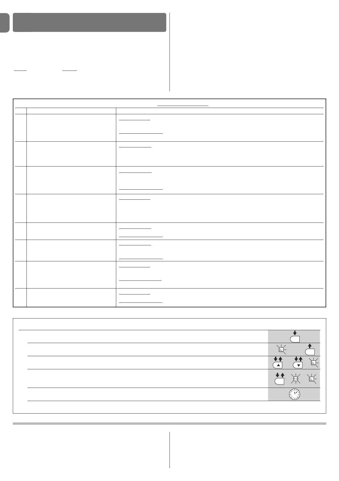
TABLE 6 - Programming procedure (first level functions)
01. Press and hold down the “Set” key for approx. 3 seconds;
02. Release the key when LED “L1” starts flashing;
03. Press the “” or “u” key to move the flashing LED to the LED representing the function to be modified;
04. Press “Set” to change the status of the function:
( short flash = OFF; long flash = ON);
05. Wait 10 seconds (maximum time) to exit the programming mode.
Note – During this procedure, points 03 and 04 need to be repeated when programming other functions to “ON” or “OFF” during the phase itself.
 Loading...