10 – ENGLISH
4.2 WIRING DIAGRAM AND DESCRIPTION OF CONNECTIONS
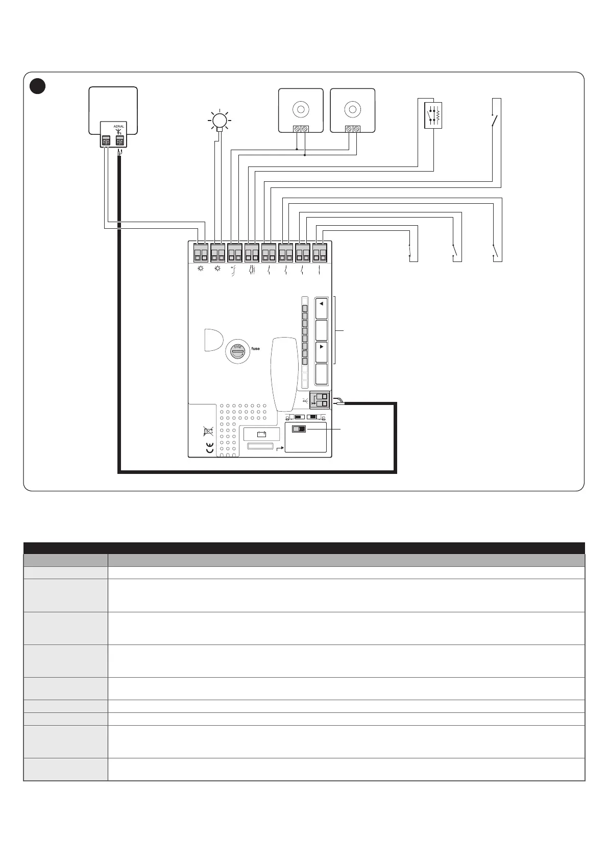
4.2.1 Wiring diagram
Receiver
KEYS
SELECTOR
LED
1.6AT
Flash
Bluebus
Stop
Sbs
Open
Aerial
Close
Aux In
L1L2L3L4L5L6L7L8
OpenStop/SetClose
OGI
FLASH
24V 4W
OGI
TX
Bluebus Bluebus
RX
CLOSE
OPEN
AUX IN
NO NO
NC
STOP
NO
NC
8K2
SBS
NO
IBT4N
17
4.2.2 Description of connections
Table 5
ELECTRICAL CONNECTIONS
Terminals Description
FLASH Output for one or two Nice or similar type warning lights with 12 V bulb only, maximum 21 W.
OGI
“Open Gate Indicator” output; a 24 V (max 4 W) signalling light can be connected.
It can also be programmed for other functions; see the “Level 2 programming (adjustable parameters)”
paragraph.
BLUEBUS
This terminal can be used to connect compatible devices, which are all connected in parallel with only two wires
carrying both the electric power and communication signals.
For further information on the BlueBUS, refer to the “BlueBUS” paragraph.
STOP
NO-NC-8K2
Input for devices that suspend or even stop the current manoeuvre; “Normally Closed” and “Normally Open”
contacts or xed resistor devices can be connected by suitably conguring the input.
For further information on the STOP function, refer to the “STOP input” paragraph.
Sbs
Input for devices that control the movement in Step-by-Step mode; it is possible to connect “Normally Open”
contacts.
OPEN
Input for devices that control the opening movement only; it is possible to connect “Normally Open” contacts.
CLOSE
Input for devices that control the closing movement only; it is possible to connect “Normally Open” contacts.
AUX_IN
(Auxiliary Input)
Input for devices that suspend or stop the current manoeuvre; “Normally Closed” contacts can be connected to
this input.
The Oview accessory can be used to modify the input’s functions; the input is factory-congured as a STOP input.
ANTENNA
Antenna connection input for radio receiver; the antenna is incorporated in the warning light; alternatively, an
external antenna can be used.
 Loading...