16 – ENGLISH
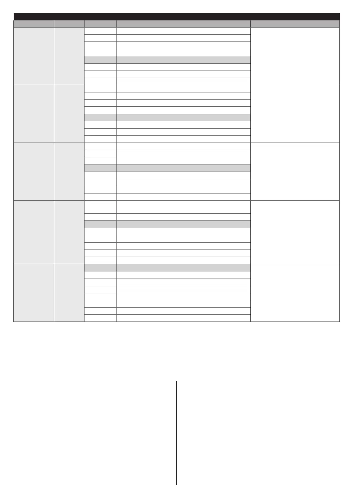
LEVEL 2 FUNCTIONS (ADJUSTABLE PARAMETERS)
Entry LED Parameter LED (level) Set value Description
L4
OGI
output
L1 “Gate Open Indicator” (G.O.I.) function
Adjusts the function associated
with the OGI output [regardless
of the associated function, the
output – when enabled – supplies
a voltage of 24 V (–30 +50%) with 4
W maximum power].
L2 Enabled if gate leaf closed
L3 Enabled if gate open
L4 Enabled with radio output no. 2
L5 Enabled with radio output no. 3
L6 Active with radio output no. 4
L7 Maintenance indicator
L8 Electric lock
L5
Motor
force
L1 Ultra-light gate
Adjusts the motor force control
system to adapt it to the gate’s
weight. The force control system
also measures the ambient
temperature and increases the
motor force automatically in case of
particularly cold temperatures.
L2 Very light gate
L3 Light gate
L4 Average gate
L5 Medium-heavy gate
L6 Heavy gate
L7 Very heavy gate
L8 Ultra-heavy gate
L6
Partial
Open
L1 0,5 mt
Adjusts the degree of partial
opening, which can be controlled
through radio command no. 2
or with “CLOSE”; if the “Close”
function is present, it switches to
“Partial Open”
L2 1 mt
L3 1,5 mt
L4 2 mt
L5 2,5 mt
L6 3 mt
L7 3,4 mt
L8 4 mt
L7
Maintenance
notice
L1
Automatic (depending on the severity of the
manoeuvres)
Adjusts the number of manoeuvres
after which the automation
maintenance request is triggered
(see the ““Maintenance notice”
function” paragraph).
L2 1000
L3 2000
L4 4000
L5 7000
L6 10000
L7 15000
L8 20000
L8
List of
malfunctions
L1 Result of 1st manoeuvre (most recent)
Allows for checking the type of
anomaly that occurred in the last
8 manoeuvres (see the “Anomaly
log” paragraph).
L2 Result of 2nd manoeuvre
L3 Result of 3rd manoeuvre
L4 Result of 4th manoeuvre
L5 Result of 5th manoeuvre
L6 Result of 6th manoeuvre
L7 Result of 7th manoeuvre
L8 Result of 8th manoeuvre
All the parameters can be adjusted as required without any contraindications; only the adjustment of the “Motor Force” could
require special attention:
– high force values should not be used to compensate for points of abnormal friction on the leaf. Excessive force can jeopardise
the operation of the safety system or damage the leaf
– if the “Motor Force” control is used to aid the impact force reduction system, measure the force again after each adjustment in
accordance with the EN 12445 standard
– wear and weather conditions may affect the gate’s movement, therefore periodic force readjustments of the motor force may be
necessary.
7.4 SPECIAL FUNCTIONS
7.4.1 “Always open” function
The “Always open” function is a control unit feature that enables
the user to always command an opening manoeuvre when the
“Step-by-Step” command lasts longer than 2 seconds; this is
useful, for example, for connecting a timer contact to the Sbs
terminal in order to keep the gate open for a certain time frame.
This feature is valid regardless of how the “Sbs” input is
programmed, unless it is programmed to perform the “Close”
function. Refer to the “Step-by-Step function” under the “Level
2 programming (adjustable parameters)” paragraph.
7.4.2 “Move anyway” function
This function can be used to operate the automation even one
or more some safety devices fail to work properly or are out of
order. The automation can be controlled in “hold-to-run” mode
by proceeding as follows:
1. send a command to operate the gate, using a transmitter
or key selector, etc. If everything functions properly, the
gate will move normally, otherwise proceed with point 2
2. within 3 seconds, press the control again and hold it down
3. after roughly 2 seconds, the gate will complete the
requested manoeuvre in “hold-to-run” mode, in other
words, it will continue to move so long as the control is
held down.
 Loading...