6 – ENGLISH
3.4 PRE-INSTALLATION WORKS
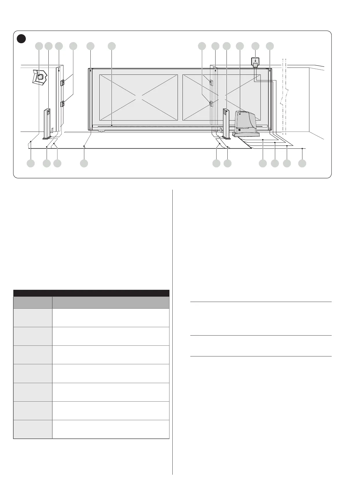
The gure shows an example of an automation system, constructed using Nice components.
A C E F G JD C H
1234546 657
BB I
4
A Key selector
B Photocells on column
C Main xed edge (optional)
D Photocells
E Main movable edge
F Rack
G Secondary xed edge (optional)
H RUN1500
I Warning light with incorporated antenna
J Secondary movable edge (optional)
These above-mentioned components are positioned according
to a typical standard layout. Using the layout in “Figure 4” as
a reference, dene the approximate position in which each
component of the system will be installed.
Table 4
TECHNICAL SPECIFICATIONS OF ELECTRICAL CABLES
Identication
no.
Cable characteristics
1
GEARMOTOR POWER SUPPLY cable
1 cable 3 x 1.5 mm
2
Maximum length 30 m [note 1]
2
WARNING LIGHT cable
1 cable 2 x 0.5 mm
2
Maximum length 20 m
3
ANTENNA cable
1 x RG58-type shielded cable
Maximum length 20 m; recommended < 5 m
4
MOVABLE EDGES cable
1 cable 2 x 0.5 mm
2
[note 4]
Maximum length 30 m [note 5]
5
FIXED EDGES cable
1 cable 2 x 0.5 mm
2
[note 4]
Maximum length 30 m
6
PHOTOCELL cable
1 cable 2 x 0.5 mm
2
Maximum length 30 m [note 2]
7
KEY SELECTOR cable
2 cables 2 x 0.5 mm
2
[note 3]
Maximum length 50 m
Note 1 If the power supply cable is longer than 30 m, a cable
with larger cross-sectional area (3 x 2.5 mm
2
) must be
used and a safety earthing system must be installed
near the automation.
Note 2 If the BlueBus cable is longer then 30 m, up to maximum
50 m, it is necessary to use a cable with a greater cross-
sectional area (2 x 1 mm
2
).
Note 3 These two cables can be replaced by a single 4 x 0.5
mm
2
cable.
Note 4 If more than one edge is present, refer to the “
STOP input” paragraph for the type of connection
recommended.
Note 5 Movable edges must be connected to sliding leaves
using special devices, which enable the connection
even when the leaf is moving.
a
Before proceeding with the installation, prepare the
required electrical cables by referring to “Figure 4”
and to the indications specied in the “TECHNICAL
SPECIFICATIONS” chapter.
a
The cables used must be suited to the type of
environment of the installation site.
a
When laying the pipes for routing the electrical
cables, take into account that any water deposits in
the junction boxes may cause the connection pipes
to form condensate inside the control unit, thus
damaging the electronic circuits.
 Loading...