18 – ENGLISH
TROUBLESHOOTING...
(troubleshooting guide)
8
8 TROUBLESHOOTING GUIDE
8.1 TROUBLESHOOTING
The table below contains useful instructions to resolve any
malfunctions or errors that may occur during installation or in
case of a fault.
L8 L 7 L 6 L5 L 4 L3 L 2 L 1
Close
Stop/Set
Open
F1
F2
28
Table 9
TROUBLESHOOTING
Problems Recommended checks
The radio transmitter does not
control the gate and the LED on the
transmitter does not light up
Check whether the transmitter batteries are exhausted and replace them if necessary.
The radio transmitter does not
control the gate but the LED on the
transmitter lights up
Check whether the transmitter has been memorised correctly in the radio receiver.
No manoeuvre starts and the
“BlueBUS” LED does not ash
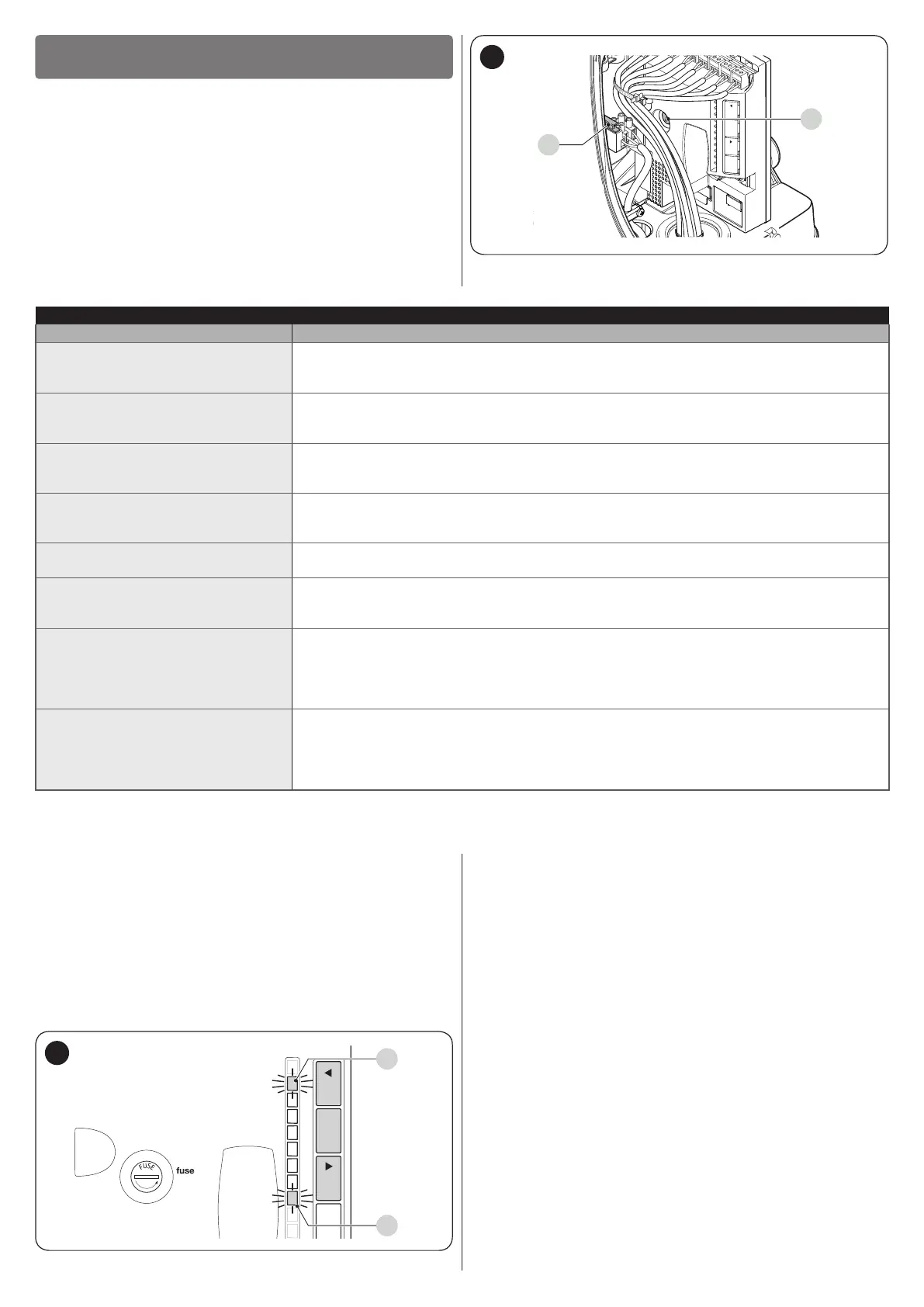
Check that the gearmotor is being powered with the mains voltage
Check whether fuses F1 and F2 are blown; if they are, identify the cause of the failure then
replace the fuses with others having the same current rating and characteristics.
No manoeuvre starts and the
warning light is off
Check that the command is actually received. If the command reaches the Step-by-Step
input, the corresponding “SbS” LED must light up; if instead the radio transmitter is used, the
“BluBus” LED must emit two quick ashes.
No manoeuvre starts and the
warning light ashes a few times
Count the number of ashes and check the corresponding value in “Table 10”.
The manoeuvre starts but is
immediately followed by a reverse
run
The selected force value may be too low to move the type of gate. Check whether there are
any obstacles and, if necessary, select a higher force.
The manoeuvre is completed
correctly but the warning light does
not work
Make sure that there is voltage on the warning light’s FLASH terminal during the manoeuvre
(being intermittent, the voltage value is not signicant: roughly 10–30 Vc); if there is
voltage, the problem is due to the lamp, which must be replaced with one having the same
characteristics; if there is no voltage, there may have been an overload on the FLASH output.
Check that the cable has not short-circuited.
The manoeuvre is completed
correctly but the OGI (Open Gate
Indicator) does not work
Check the type of function programmed for the OGI output (“Table 7”).
When the indicator light should be lit, check that there is voltage on the OGI terminal (roughly
24 Vc); if there is voltage, the problem is due to the indicator light, which must be replaced
with one having the same characteristics; if there is no voltage, there may have been an
overload on the OGI output. Check that the cable has not short-circuited.
8.2 ANOMALY LOG
The gearmotor allows for displaying any anomalies that
occurred in the last 8 manoeuvres, for example, the interruption
of a manoeuvre due to the intervention of a photocell or sensitive
edge.
To do this:
1. press and hold the
g
button until LED “L1” starts
ashing
2. release the
g
button when LED “L1” starts
ashing
1.6AT
L1L2L3L4L5L6L7L8
OpenStop/SetClose
L1
L8
29
3. press the
f
or
h
button to shift the
ashing LED to “L8”, that is, the “entry LED” for the “List
of anomalies” parameter
4. press and hold the
g
button. With the
g
button pressed:
– wait roughly 3 seconds, after which the LEDs
corresponding to the manoeuvres that had anomalies
will light up. LED L1 indicates the result of the most
recent manoeuvre, while LED L8 indicates the result of
the eighth manoeuvre. If the LED is lit, it means that
anomalies occurred during the manoeuvre; if the LED
is off, the manoeuvre terminated without any anomalies
– press the
f
or
h
button to select the
desired manoeuvre: the corresponding LED will ash
the same number of times as those emitted by the
warning light following an anomaly (see “Table 10”)
5. release the
g
button.
 Loading...