ENGLISH – 21
FURTHER INFORMATION
(Accessories)
9
9 FURTHER DETAILS (Accessories)
9.1 ADDING OR REMOVING DEVICES
Once the automation has been assembled, it is possible to
add or remove devices at any time. In particular, various types
of devices can be connected to the “BlueBUS” and “STOP”
inputs, as described in the following paragraphs.
m
After having added or removed devices, these must
be learned as described in the “Learning of other
devices” paragraph.
9.1.1 BlueBUS
BlueBUS is a technique that allows for connecting compatible
devices with only two wires which carry the electrical power and
the communication signals. All devices are connected in parallel
on the same 2 BlueBUS wires and without having to observe the
polarities; each device is recognised because it is assigned a
univocal address during the installation phase.
The following devices can be connected to the BlueBUS:
photocells, safety devices, control buttons, signalling lights,
etc. The control unit recognises all the connected devices
individually through an appropriate learning phase, and can
detect all possible anomalies with absolute precision.
For this reason, whenever a device is connected to or removed
from BlueBUS, the learning phase must be carried out on the
control unit, as described in the “Learning of other devices”
paragraph.
9.1.2 STOP input
STOP is the input that causes immediate stoppage of the
manoeuvre followed by its brief reversal. Devices with output
featuring normally open “NO” and normally closed “NC”
contacts, as well as devices with 8.2 kΩ xed resistor output,
such as sensitive edges, can be connected to this input.
As with the BlueBUS, the control unit recognises the type of
device connected to the STOP input during the learning phase
(see the “Learning of other devices” paragraph); subsequently
the control unit gives a STOP command when it detects a
variation with respect to the recognised status.
Multiple devices, even of different types, can be connected to
the STOP input if suitable arrangements are made:
– Any number of NO devices can be connected to each other
in parallel.
– Any number of NC devices can be connected to each other
in series.
– Two devices with 8.2 kΩ xed resistor output can be connected
in parallel; if there are more than 2 devices then they must all
be connected in cascade, with a single 8.2 kΩ terminating
resistor.
– It is possible to combine two NO and NC contacts by placing
them in parallel, while also mounting a 8.2 kΩ resistor in series
with the NC contact (this also allows for combining 3 devices:
NA, NC and 8.2 kΩ).
a
If the STOP input is used to connect devices with
safety functions, only those devices with 8.2 kΩ
xed resistor guarantee Category 3 safety against
faults in accordance with the EN 13849-1 standard.
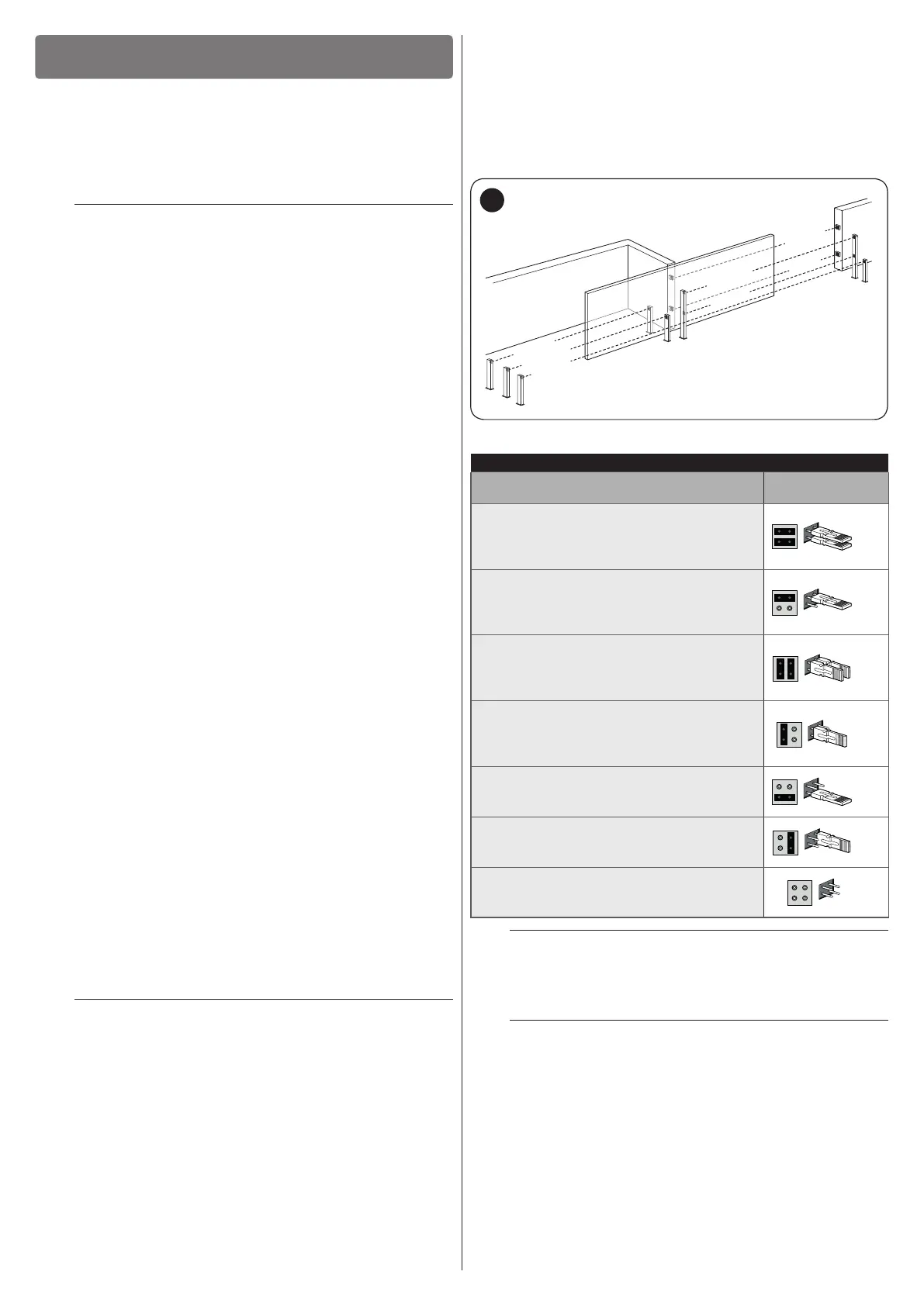
9.1.3 Photocells
To allow the control unit to recognise the devices connected
through the “BlueBUS” system, these devices must be
addressed.
This operation can be carried out by correctly positioning
the electrical jumper present in each device (also refer to
the instruction manual of each device). Shown below is an
addressing diagram for photocells, based on their type.
FOTO 2
FOTO 1 II
FOTO 1
FOTO
FOTO II
FOTO 2 II
FOTO 3
31
Table 13
PHOTOCELL ADDRESSES
Photocell
Position of the
jumpers
FOTO (PHOTO)
External photocell h = 50 activated during
the closing phase (stops and reverses the
gate’s movement)
FOTO II (PHOTO II)
External photocell h = 100 activated
during the closing phase (stops and
reverses the gate’s movement)
FOTO 1 (PHOTO 1)
Internal photocell h = 50 activated during
the closing phase (stops and reverses the
gate’s movement)
FOTO 1 II (PHOTO 1 II)
Internal photocell h = 100 activated during
the closing phase (stops and reverses the
gate’s movement)
FOTO 2 (PHOTO 2)
External photocell activated during the
opening phase
FOTO 2 II (PHOTO 2 II)
Internal photocell activated during the
opening phase
FOTO 3 (PHOTO 3)
Single photocell covering the entire
automation
a
In order to jointly install PHOTO 3 and PHOTO II, the
position of the elements making up the photocell
(TX - RX) must comply with the warning indicated in
the instruction manual of the photocells.
m
At the end of the installation procedure, or after
photocells or other devices have been removed,
it is necessary to complete the learning procedure
(see the “Device learning” paragraph).
 Loading...