26 – ENGLISH
FURTHER INFORMATION
(Accessories)
9
9 FURTHER DETAILS (Accessories)
9.1 MODIFYING THE STOP INPUT
CONFIGURATION
STOP is the input that causes immediate stoppage of the manoeu-
vre followed by its brief reversal. Devices with output featuring nor-
mally open “NO” and normally closed “NC” contacts, as well as
devices with 8.2 kΩ xed resistor output, such as sensitive edges,
can be connected to this input.
As with the BlueBUS, the control unit recognises the type of device
connected to the STOP input during the learning phase (see the “
Device learning” paragraph); subsequently the control unit gives
a STOP command when it detects a variation with respect to the
learned status.
Multiple devices, even of different types, can be connected to the
STOP input if suitable arrangements are made:
– Any number of NO devices can be connected to each other in
parallel.
– Any number of NC devices can be connected to each other in
series.
– Two devices with 8.2 kΩ xed resistor output can be connected
in parallel; if there are more than 2 devices then they must all be
connected in cascade, with a single 8.2 kΩ terminating resistor.
– It is possible to combine two NO and NC contacts by placing
them in parallel, while also mounting a 8.2 kΩ resistor in series
with the NC contact (this also allows for combining 3 devices:
NA, NC and 8.2 kΩ).
a
If the STOP input is used to connect devices with
safety functions, only those devices with 8.2 kΩ
xed resistor guarantee Category 3 safety against
faults in accordance with the EN 13849-1 standard.
9.2 ALARM SYSTEM
Congured control units, and those identied with code ***/V1,
have an integrated alarm system that activates following 2 consec-
utive obstacle detections, or sensitive edge interventions, during
the manoeuvre.
The moment the automation reaches the closed position, the alarm
system resets and prepares for subsequent manoeuvres.
After two interventions as described above, the control unit inhib-
its any movement by activating the automation’s permanent lock
and triggering the siren (connected to the ALARM terminal) for 5
minutes.
To unlock the automation and silence the siren, (any) one of the
following must occur: the STOP button on the control panel is
pressed, the sensitive edge is pressed, the contact on the SbS
terminal is triggered (with the motor stopped) or the contact on the
STOP terminal (NC) is triggered. From then onwards, the control
unit will resume its normal operation.
The start of each closing manoeuvre (commanded from a radio
transmitter or Oview Terminal) is preceded by a pre-ashing se-
quence and by the activation of the siren for 5 seconds (non-ex-
cludable), after which the motor will start.
l
In the event of a power supply failure during the
automation’s permanent lock condition, the alarm
system will re-emit the acoustic and visual signals
for 5 minutes at the next re-start of the control unit.
a
The alarm system is active by default and can be
deactivated by the user: please note, however, that
in this case the control unit will no longer be com-
pliant with standard UL325.
If required, the alarm siren can be disconnected and the ALARM
output can be recongured for other applications: in this case the
alarm will be disabled, but all the other safety systems required to
detect obstacles will remain active.
The alarm system can be activated/deactivated using the Oview
programmer (see paragraph “Connecting the Oview program-
mer“).
9.3 CONNECTING AN SM-TYPE RADIO RECEIVER
The control unit has a slot for mounting radio receivers with SM
connector (optional accessories) belonging to the SMXI, SMXIS,
OXI, etc. families, which can be used to remotely control the con-
trol unit through transmitters that intervene on the control unit’s
inputs.
f
Before installing a receiver, disconnect the power
supply to the control unit.
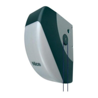
To install a receiver ("Figure 30"):
1. insert the receiver (A) in the appropriate slot (B) on the con-
trol unit’s electronic board.
B
A
30
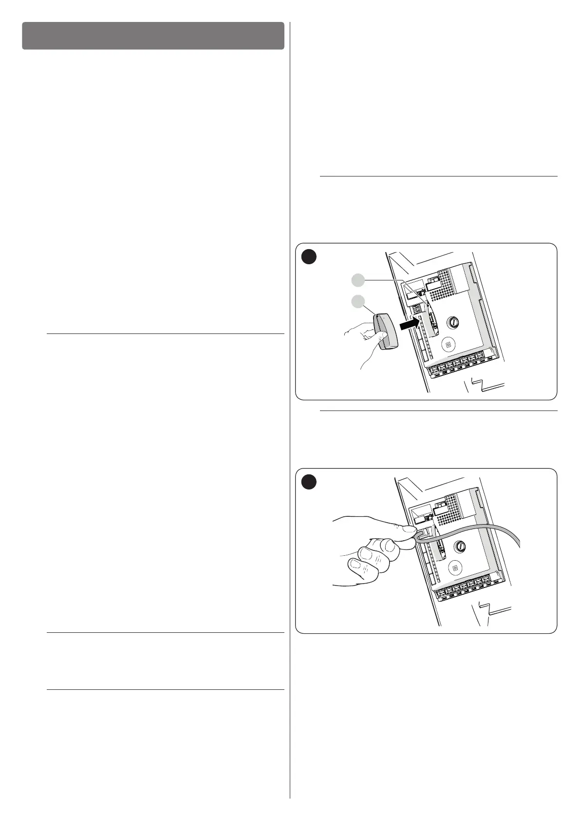
l
If the aerial incorporated in LUCYB or other type
of external aerial is not used, screw the rigid cable
supplied with the receiver onto the aerial terminal
(“Figure 31”):
31
The association between the radio receiver output and the com-
mand executed by the motor is shown in “Table 17”: