ENGLISH – 7
3.5 PRE-INSTALLATION WORKS
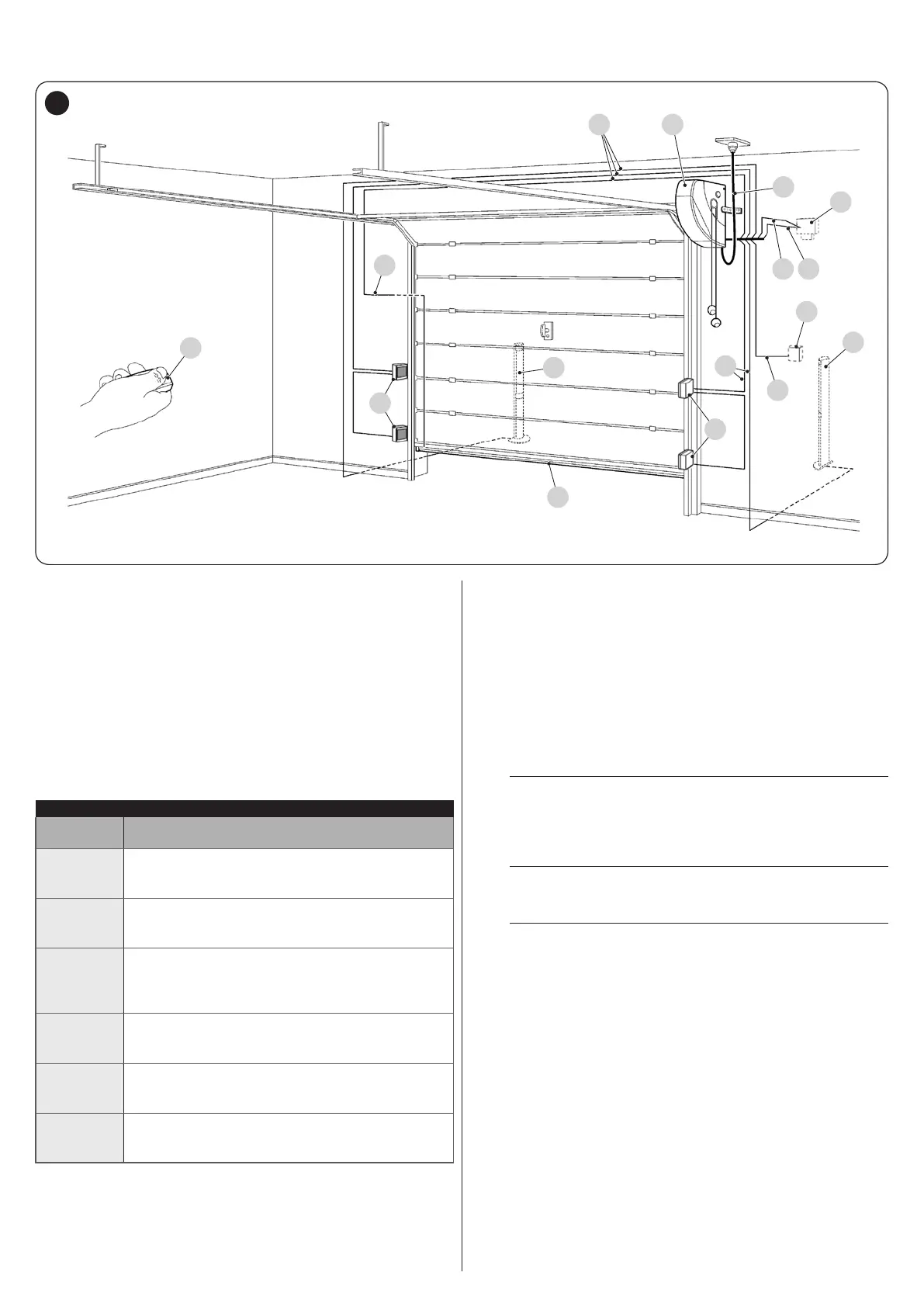
The gure shows an example of an automation system, constructed using Nice components.
A4
C
5
4
E
1
2 3
F
D
D
6
G
B
B
5
A Gearmotor
B Photocells
C Wall-mounted push-button panel
D Photocells on column
E Warning light with incorporated antenna
F Transmitter
G Main edge
These above-mentioned components are positioned according to
a typical standard layout. Using the layout in “Figure 5” as a refer-
ence, dene the approximate position in which each component of
the system will be installed.
Table 4
TECHNICAL SPECIFICATIONS OF ELECTRICAL CABLES
Identication
no.
Cable characteristics
1
GEARMOTOR POWER SUPPLY cable
1 cable 3 x 15 AWG (3 x 1,5 mm
2
)
Maximum length 98ft 5in 7/64 (30 m) [note 1]
2
WARNING LIGHT cable
1 cable 2 x 17 AWG (2 x 1 mm
2
)
Maximum length 65ft 7in 13/32 (20 m)
3
ANTENNA cable
1 x RG58-type shielded cable
Maximum length 65ft 7in 13/32 (20 m);
recommended < 16ft 4in 55/64 (5 m)
4
PHOTOCELL cable
1 cable 2 x 20 AWG (2 x 0,5 mm
2
)
Maximum length 98ft 5in 7/64 (30 m) [note 2]
5
WALL-MOUNTED PUSH-BUTTON PANEL cable
2 cables 2 x 20 AWG (2 x 0,5 mm
2
) [note 3]
Maximum length 164ft 1/2in (50 m)
6
MAIN EDGE cable
1 cable 2 x 20 AWG (2 x 0,5 mm
2
)
Maximum length 65ft 7in 13/32 (20 m)
Note 1 If the power supply cable is longer than 98ft 5in 7/64 (30
m), a cable with larger cross-sectional area (3 x 13 AWG
(3 x 2,5 mm
2
)) must be used and a safety earthing system
must be installed near the automation.
Note 2 If the BlueBus cable is longer then 98ft 5in 7/64 (30 m),
up to maximum 164ft 1/2in (50 m), it is necessary to use a
cable with a greater cross-sectional area (2 x 17 AWG (2 x
1 mm
2
)).
Note 3 These two cables can be replaced by a single 4 x 20 AWG
(4 x 0,5 mm
2
) cable.
a
Before proceeding with the installation, prepare the
required electrical cables by referring to “Figure 5”
and to that stated in the “TECHNICAL SPECIFICA-
TIONS” chapter.
a
The cables used must be suited to the type of envi-
ronment of the installation site.
a
When laying the pipes for routing the electrical ca-
bles, take into account that any water deposits in
the junction boxes may cause the connection pipes
to form condensate inside the control unit, thus
damaging the electronic circuits.