3 F600 Step By Step Guide
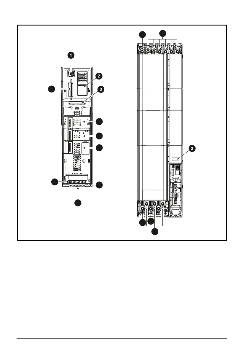
Figure 1-2 Feature diagram for frame size 11
Key
1. Keypad connection 8. Control connections
2. Rating label 9. Communications port
3. Identification label 10. NV media card slot
4. Option module slot 1 11. Ground connections
5. Option module slot 2 12. AC supply connections*
6. Option module slot 3 13. DC bus +
7. Relay connections 14. Motor connections
*Common AC Supply connections are internally linked on the 11E 6 pulse drive