33
II. Microscopy Method
8 Adjust the field diaphragm and the aperture diaphragm.
• Generally, decrease the size of the aperture diaphragm to approximately 70 to 80% of the
numerical aperture of the objective. (See Page 54.)
• Decrease the size of the field diaphragm so that it inscribes or circumscribes the viewfield.
(See Page 54.)
9 Adjust the orientation of the polarizer by rotating the rotatable polarizer for the diascopic
illumination and adjust the contrast of DIC contrast images. (See Page 59.)
• The background of the field of view can be adjusted to a gray sensitive color. This adjustment
improves the contrast of the image.
• The direction of the contrast is the shearing direction (45 degrees, from the left far side to the
right near side, viewed from the top of the microscope).
Rotate the specimen or the stage to get an adequate gradation in the shearing direction.
UE
PI2A
USB
RS
2
3
2
C
LCN
T
N
D
8
N
C
B
F
.
S
.
7
5
3
7
0
1
J
A
P
A
N
A
chr
N
.
A
=
0
.
9
JAPAN
0
.
8
0
.
7
0
.6
0
.
5
0
.
4
0
.
3
0.2
0.1
3
x
2
S
T
A
G
E
J
A
P
A
N
J
A
P
A
N
69
6
001
3
x
2
S
T
A
G
E
J
A
P
A
N
F
.
STOP
J
A
P
A
N
BF DF FL1 FL2
FL1
FL2
1
0
02
0
0
1
0
0
I
N
OUT
L
V
-
T
T2
2
1
4
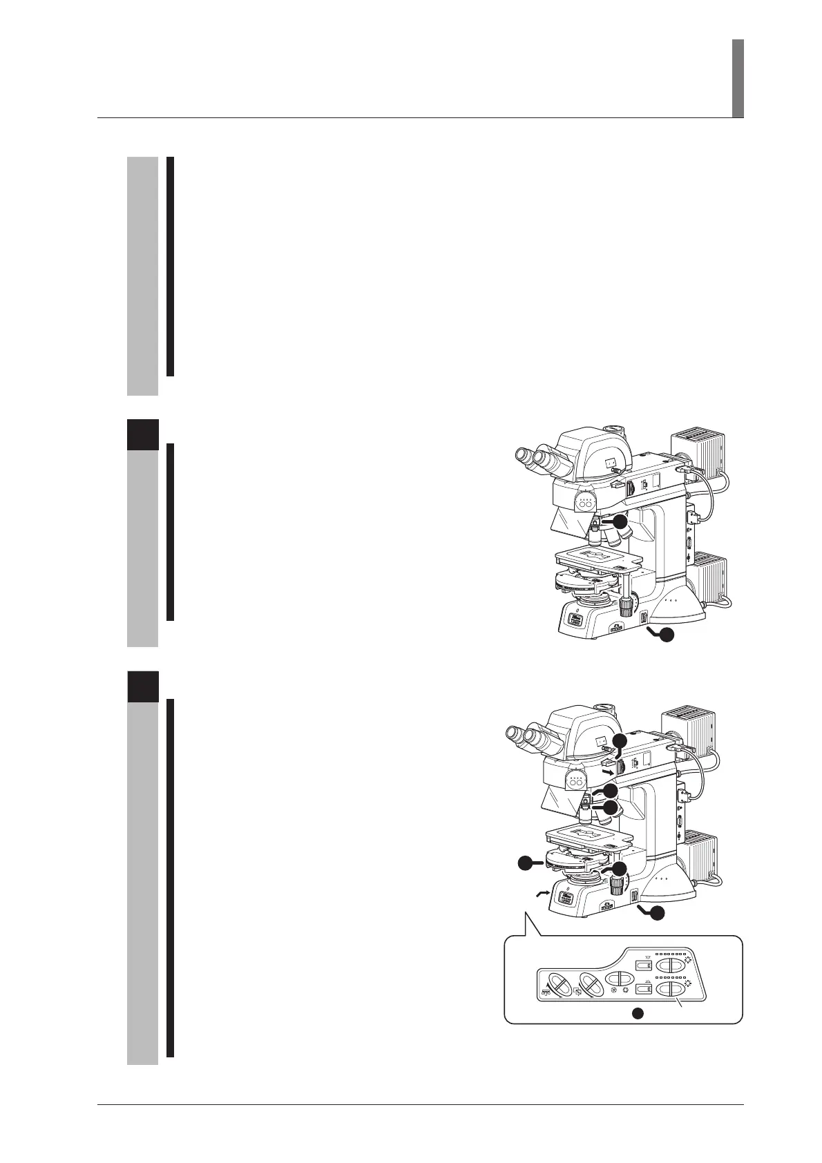
If necessary, perform the sensitive color microscopy.
1 Place the NCB filter into the optical path.
(See Page 44.)
2 Push in the lambda plate slider to locate the
lambda plate into the optical path. (See Page 63.)
The background of the field of view becomes a
sensitive color. The color improves the color
contrast of the image and is useful for
observations. As the refractive index or the
thickness of the specimen varies, the interference
color of the specimen changes.
U
E
P
I2
A
USB
RS
2
3
2C
L
CN
T
N
D
8
N
C
B
F
.
S
.
7
5
3
7
0
1
J
A
P
A
N
A
chr
N
.
A
=
0
.
9
JAPAN
0
.
8
0
.
7
0
.6
0
.
5
0
.
4
0
.
3
0.2
0.1
3
x
2
S
T
A
G
E
J
A
P
A
N
J
A
P
A
N
696001
3
x
2
S
T
A
G
E
J
A
P
A
N
F
.
STO
P
J
A
P
A
N
BF DF FL1 FL2
FL1
FL2
1
0
02
0
0
10
0
IN
OUT
LV
-
T
T2
OBJ.
CUBE
A.S.
EPI
DIA
EPI
DIA
1
3
5
2
4
6
7
DIA brightness switch
Operation
panel
5
Return to the bright-field microscopy under the diascopic illumination.
1 Pull out the analyzer slider to move the analyzer
away from the optical path. (See Page 60.)
2 Swing out the upper part of the rotatable
polarizer for the diascopic illumination to move
the polarizer away from the optical path.
(See Page 59.)
3 Pull out the DIC slider to move the objective
DIC prism away from the optical path.
(See Page 66.)
4 Set the condenser turret to the “O” position to
move the condenser DIC prism away from the
optical path. (See Page 55.)
5 Pull out the lambda plate slider and move the
lambda plate away from the optical path.
(See Page 63.)
6 Operate the DIA brightness switch on the
operation panel to adjust the brightness of the
diascopic illumination. (See Page 42.)
7 Adjust the brightness with the ND filter. (See Page 44.)